
Applications Guide
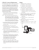
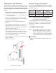
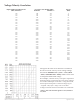
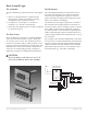
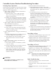
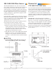
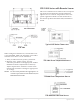
Table Of Contents
- CEP-4000 General Information
- SSE-1000/2000 Flow Sensors
- Thermostats
- VAV Single Duct Cooling/Heating Applications
- VAV Dual Duct Cooling/Heating Applications
- Index

CEP-4000 Series VAV Flow Controller-Actuators 8 Applications Guide
Controller/System Checkout/Troubleshooting Procedure
5. Check mechanical movement issues.
A. If the damper does not move, observe the
CEP’s drive sha for rotation. If it rotates, but
the damper does not, tighten the setscrews
and retry.
C. If it still does not move, loosen the two
setscrews on the sha (or remove the CEP)
and verify that the damper can move freely
through a full range of motion on its own. Fix
any binding of the damper and retighten the
setscrews.
D. Verify the damper is not at the end of its
travel. Change “Requested Flow“ to make
the CEP drive the opposite direction (via
thermostat or overriding the controller).
Loosen the two setscrews and reposition the
damper sha.
E. Verify correct rotation direction. Swap the red
and blue motor wires on terminals 12 and 14
to reverse the rotation if necessary. (See the
Rotation Setup section.)
Overriding to Open
1. To drive the controller/damper open, remove the
wiring from terminal 6 “Requested Flow.”
2. Jumper terminal 5 (9.1 VDC) to terminal 6. This
commands the unit to control at 3000 fpm (full
airow). (Assuming the actual ow is less than
3000 fpm, the unit should open damper.)
Overriding to Closed
1. To drive the controller/damper closed, remove the
wiring from terminal 6 “Requested Flow.”
2. Jumper 4 (–) to terminal 6. This commands the
unit to control at zero fpm. (Assuming the actual
ow is more than 0 fpm, the unit should close the
damper.)
NOTE: A magnetic slip-clutch inside the actuator
allows motor to continue running even
when end-stops have been reached.
Other Troubleshooting
1. Check the wiring for correct connections and
loose or broken wires.
2. Check the sensor. See the SSE Series Flow Sensors
section.
3. Check the thermostat. See the Thermostats
section.
CAUTION
Never jumper Terminal 4 to Terminal 5 since
this would cause a dead short.
Verifying Proper Operation
The following set-up guide is directed towards single
duct cooling applications, the same concepts can be
applied to other congurations.
1. Verify supply voltage of 24 VAC at terminals 10
(phase) and 9 (ground).
A. Tolerance can be –15% to +20% (20.4–28.8
VAC). If the voltage is outside this range,
replace the transformer.
B. If there is no voltage, be sure power is turned
on. If power is turned on, turn power o and
determine why the transformer was damaged
before replacing it and turning power back on.
2. Verify supply voltage to the thermostat of 9.1
VDC at terminals 5 (+) and 4 (–).
A. Power supply to thermostat tolerance is
8.7–9.6 VDC.
B. If not correct, disconnect the thermostat and
recheck. If voltage is still not within tolerance,
replace the CEP controller.
3. Check “Requested Flow” voltage on terminal 6 (+)
and 4 (–).
A. See the Voltage/Velocity Correlation section to
correlate voltage into feet per minute.
B. If the reading is not what is desired, see the
Thermostats section to check out and/or
adjust.
4. Check “Actual Flow” voltage on terminal 2 (+)
and 4 (–) for (9–18 VDC).
A. You can also measure on terminal 7 (+) and 4
(–) for (1–5 VDC).
B. See the Voltage/Velocity Correlation section to
correlate voltage into feet per minute.
C. If the result is not logical or realistic (within
about 50 fpm), check the sensor (see the SSE
Series Flow Sensors section) and/or replace/
calibrate controller.