
Applications Guide
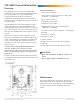
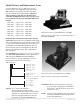
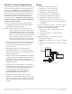
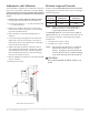
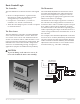
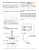
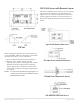
Table Of Contents
- CEP-4000 General Information
- SSE-1000/2000 Flow Sensors
- Thermostats
- VAV Single Duct Cooling/Heating Applications
- VAV Dual Duct Cooling/Heating Applications
- Index

CEP-4000 Series VAV Flow Controller-Actuators 9 Applications Guide
Thermostats
CTE-1000/1100/5000 Series
The CTE-1000/1100/5000 series thermostats operate
on a 9.1 VDC power supply from the CEP controller
and output a 0–6 VDC signal on the T(x) terminals.
See the Applications sections for details on which
“T” terminals are used for each model thermostat.
Generally T1/T3 are used for the cooling mode and
T2/T4 for heating. T1 and T2 are adjustable; T3 and
T4 are xed.
Terminal “R” (on the thermostat) is available to
provide a ow override command—such as forcing
the box to a “close-o“ on a dual-duct application.
Any voltage (1–6 VDC) applied to the “R1” terminal
subtracts that value from the “T1” signal. Similarly,
use “R2” to subtract from the “T2” signal. If this
function is not being used, a factory-installed jumper
connects the appropriate “R” terminal to ground (–)
for zero oset.
SSE-1000/2000 Flow Sensors
The SSE-1000/2000 series are “hot wire anemom-
eter” sensors. The sensor consists of two coils of wire
mounted in the air stream: one monitors airow,
while the other is a reference used for duct tempera-
ture compensation. The SSE-2000 series sensors also
include a temperature sensor for use with heating/
cooling “changeover” applications (requires an ad-
ditional relay module).
Each CEP-4000 is calibrated to its SSE series sensor at
the factory. No further calibration is needed. If the
units are replaced or become mismatched, see the
Adjustments and Calibration section.
The SSE series ow sensor can be tested by measur-
ing resistance between terminals 1 and 3.
1. Disconnect ALL wiring from the SSE sensor.
2. Measure resistance between terminals 1 and 3
with an ohmmeter. Resistance should be between
100–400 ohms. If not, replace the sensor and
recalibrate controller to the new sensor. See the
Adjustments and Calibration section.
3. SSE-2000 series sensors have additional terminals
marked “X” and “Y” for use with the heat/cool
changeover relay module. Resistance between
“X” and “Y” should be between 2,000 and 20,000
ohms.
CAUTION
To prevent damage to the SSE series sensors, do
not touch or handle the interior wire windings.
CTE-1101