
Applications Guide

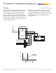

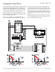
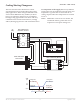
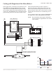
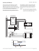

Table Of Contents
- CEP-4000 General Information
- SSE-1000/2000 Flow Sensors
- Thermostats
- VAV Single Duct Cooling/Heating Applications
- VAV Dual Duct Cooling/Heating Applications
- Index

CEP-4000 Series VAV Flow Controller-Actuators 11 Applications Guide
Thermostat Troubleshooting
1. Verify MIN VELOCITY voltage:
A. Adjust the CTE series thermostat’s setpoint
slider for minimum airow.
B. Verify the minimum setpoint adjustment
capability by reading the thermostat voltage
output (at the CEP terminals 4 and 6 or the
equivalent connections on the thermostat
terminals using the front meter taps and
HSO-5001 meter leads), adjusting the MIN
VELOCITY potentiometer fully clockwise,
and measuring a maximum voltage setpoint
between 6.0 and 7.5 VDC.
C. Then adjust the MIN VELOCITY potentiome-
ter fully counterclockwise and verify a mini-
mum voltage setpoint between 0 and 0.5 VDC.
D. Leave the MIN VELOCITY setpoint temporar-
ily at minimum voltage. If the thermostat’s
MIN VELOCITY cannot adjust from 0.5 to 6.0
VDC, then replace the thermostat.
2. Verify MAX VELOCITY voltage:
A. Adjust the CTE series thermostat’s setpoint
slider for maximum airow.
B. Verify the maximum setpoint adjustment
capability by reading the thermostat voltage
output, adjusting the MAX VELOCITY
potentiometer fully counterclockwise, and
measuring a minimum voltage setpoint
between 0 and 0.5 VDC.
C. Then adjust the MAX VELOCITY potentiom-
eter fully clockwise and verify a minimum
voltage setpoint between 6.0 and 7.5 VDC.
D. Leave the MAX VELOCITY setpoint
temporarily at maximum voltage. If the
thermostat’s MAX VELOCITY cannot adjust
from 0.5 to 6.0 VDC, replace the thermostat.
3. Verify fully open and fully closed positions:
A. With the MIN VELOCITY setpoint adjusted
for no ow and the MAX VELOCITY setpoint
adjusted for full ow, adjust the thermostat’s
setpoint slider for minimum airow (no ow).
B. Verify the CEP positions the damper to the
fully closed position.
C. Aer the damper is fully closed, adjust the
thermostat’s setpoint slider for maximum
airow (full ow).
D. Verify the CEP positions the damper to the
fully open position.
4. If the CEP does not position the damper to the
fully open or fully closed position, verify the
following mechanical issues:
A. Are upstream velocities capable of achieving
3000 fpm? If not, x obstructions or restric-
tions to increase airow (if practical) or take
reduced airow into account for expected
readings.
B. Are there any mechanical stops or binding
limiting the travel of the damper in either di-
rection? If so, adjust or repair. Repeat step 3.
C. Is the damper’s travel being limited by the
CEP’s internal stops? If so, loosen the two
setscrews and sychronize the actuator with
the sha (i.e., the CEP is fully open when the
damper is fully open). Repeat step 3.
5. If the CEP will not turn in either direction when
the setpoint slider calls for a change in airow,
verify correct voltage to the motors:
A. 24 VAC voltage is applied (the red/blue wire
on terminal 12/14 and the white wire on
terminal 11) to the motor.
NOTE: Whenever the motor is called to run, there
should be voltage on both 12 and 14 in
reference to 11. These voltages, however,
are phase-shied through a capacitor.
B. If either or both of the wiring leads/terminals
do not have the 24 VAC, replace the CEP and
calibrate the new CEP with the sensor. Repeat
all of the above steps.
6. Aer the operation of the system has been
veried, return the MIN VELOCITY and MAX
VELOCITY setpoints to their correct voltages.