
Applications Guide
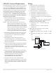
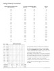
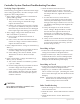
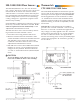
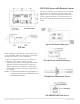
Table Of Contents
- CEP-4000 General Information
- SSE-1000/2000 Flow Sensors
- Thermostats
- VAV Single Duct Cooling/Heating Applications
- VAV Dual Duct Cooling/Heating Applications
- Index

CEP-4000 Series VAV Flow Controller-Actuators 6 Applications Guide
Velocity
(FPM)
0
20
40
65
95
130
175
225
290
370
450
550
650
760
875
1000
1133
1267
1400
1533
1667
1800
1933
2067
2200
2333
2467
2600
2733
2867
3000
Requested Flow from Thermostat
(VDC) Terminal 6*
3.00
3.10
3.20
3.30
3.40
3.50
3.60
3.70
3.80
3.90
4.00
4.10
4.20
4.30
4.40
4.50
4.60
4.70
4.80
4.90
5.00
5.10
5.20
5.30
5.40
5.50
5.60
5.70
5.80
5.90
6.00
Voltages in the chart are in reference to terminal 4.
For more accurate velocity versus voltage seings,
the formula
DESIRED VDC = [(VDC1 – VDC2)/(FPM1
– FPM2) x (DESIRED FPM – FPM2)] + VDC2 can be used
to interpolate the desired voltage.
For example,
a desired velocity of 575 fpm is required for
minimum seing, but the chart above only shows 550 fpm
at 4.10 VDC and 650 fpm at 4.20 VDC. Using the formula,
the 575 fpm should equate to a desired voltage of [(4.2
– 4.1)/(650 – 550) x (575 – 550)] + 4.10 = 4.125 VDC.
*Voltage increments shown for terminal 6 are in 0.10 VDC.
**Prior to date code 9321 this signal was 0–5 (instead of
1–5) VDC.
Voltage/Velocity Correlation
Terminal 7**
1.00
1.13
1.27
1.40
1.53
1.67
1.80
1.93
2.07
2.20
2.33
2.47
2.60
2.73
2.87
3.00
3.13
3.27
3.40
3.53
3.67
3.80
3.93
4.07
4.20
4.33
4.47
4.60
4.73
4.87
5.00
Terminal 2
9.00
9.30
9.60
9.90
10.20
10.50
10.80
11.10
11.40
11.70
12.00
12.30
12.60
12.90
13.20
13.50
13.80
14.10
14.40
14.70
15.00
15.30
15.60
15.90
16.20
16.50
16.80
17.10
17.40
17.70
18.00
Live Flow Sensor Reading (VDC)