
Install Instructions

Installation Guide
P-E Switches
CCE-1000 Series
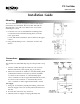
Mounting
The CCE-1000 Series are not position sensitive and may be
mounted in any orientation. The CCE–1001 and 1002 are
shipped with a case and cover. Remove the cover before
mounting the switch.
1. Locate the two 3/16" (5 mm) diameter mounting holes.
a. CCE-1001 and CCE-1002 mounting holes are in the
case’s upper back.
b. CCE-1003 and CCE-1004 use the two holes in the upper
corners
2. Using self-threading screws, mount the switch to the
surface.
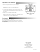
Connections
Electrical
For models CCE-1003/1004 skip step one and proceed to step
two.
1. Connect conduit through one of the two 1/2" (13 mm)
diameter knockouts. One snap-in plug is provided
2. Electrical connection are made to 8–32 UNC binding head
combination terminal screw and cup washer terminals
a. Connect to the Common “C” and Normally Open
“N.O.” terminals if a fall in signal should break the circuit.
b. Connect to the Common “C’ and Normally Closed
“N.C.” terminal if a fall in signal should make a circuit.
Air Supply
1. Using 1/4" (6 mm) O.D. polyethylene tubing, connect the
main air supply to the 3/16" (5 mm) inlet in the bottom of
the unit.
2. Provide unit with clean, dry control air
3. Limit the main air supply to 30 psig (207 kPa) max.