
Install Instructions


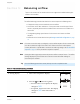
Table Of Contents
- Contents
- Section 1: About the controllers
- Section 2: Installing the controllers
- Section 3: Changing the room setpoint
- Section 4: Configuring the controllers
- Section 5: Balancing airflow
- Section 6: Application drawings
- Section 7: Sequences of operation
- Section 8: System integration and networking
- Appendix A: K-factors
- Index

S ect i on 5: Balancing airflow
Topics in this section are for control technicians or engineers who will be balancing the
airflow in the controllers.
The airflow balancing procedure described in this section requires the following items.
l A flow hood or other accurate method to measure airflow.
l An STE-8001 or STE-8201 wall sensor. If the system does not include one of these
sensors, temporarily disconnect the installed sensor and connect an STE-8001 as a
service tool.
l The engineering design specifications for the minimum and maximum airflow
setpoints.
l Password 2 which is described in the topic Getting started with configuration on page
24.
Note: If the VAV unit is a heat only or cooling only unit, the airflow setpoints for the unused mode
must be set within the range of the mode in use. Failure to set the unused setpoints
correctly will result in unpredictable or erroneous air balancing settings. See Set the airflow
setpoints on page 32 for the procedure to adjust the setpoints.
Note: Starting the balancing procedure erases all previous airflow correction factors. The airflow
readings displayed by the STE-8001 are the actual uncorrected airflow readings as
measured by the controller.
Tip: Once the following procedure is started, all steps must be completed in order.
Procedure Steps STE display
1 Starting display
1. Start at the temperature display.
2. Press the and buttons together.
l If Password 2 is not required, the display
changes to CNFG.
l If required, enter Password 2. The display
changes to CNFG when Password 2 is
correct.
72
12S1
PSW2
OOOO
Table 5–1 The airflow balancing procedure
SimplyVAV
Revision G 40