
Install Instructions


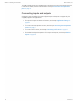


Table Of Contents
- Contents
- Section 1: About the controllers
- Section 2: Installing the controllers
- Section 3: Changing the room setpoint
- Section 4: Configuring the controllers
- Section 5: Balancing airflow
- Section 6: Application drawings
- Section 7: Sequences of operation
- Section 8: System integration and networking
- Appendix A: K-factors
- Index

Connecting a DAT sensor
The Discharge Air Temperature sensor is required for automatic changeover and for VAV
terminal units with reheat.
Illustration 2–5 Discharge air temperature sensor location
DAT sensor
Prefered location
DAT sensor
Changeover only
Connect a 10 kΩ, Type 3 thermistor temperature probe to the discharge air temperature
input. The input includes the internal pull-up resistor. An STE-1401 sensor is suitable for this
application. Follow the instructions supplied with the sensor for installation.
l For DAT limiting and reheat, install the sensor in the airflow after the reheat unit. See
the topic, Advanced options on page 35 to enable discharge air temperature control.
l When the DAT sensor is used only to detect primary air temperature, the sensor can be
placed in either location shown in the illustration Discharge air temperature sensor
location.
Illustration 2–6 Discharge air temperature input details
T
COMM
READY
AI1
GND
AO4
AO3
Section 2: Installing the controllers KMC Controls, Inc.
18 Revision G