
Install Instructions


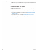


Table Of Contents
- Contents
- Section 1: About the controllers
- Section 2: Installing the controllers
- Section 3: Changing the room setpoint
- Section 4: Configuring the controllers
- Section 5: Balancing airflow
- Section 6: Application drawings
- Section 7: Sequences of operation
- Section 8: System integration and networking
- Appendix A: K-factors
- Index

Illustration 2–2 Controls and indicators
ON CTS
1 2
COMM
READY
AI1
AI5
GND
AO4
AO3
SC
BO8
BO5
BO6
SC
BO7
24VAC
AI6
GND
AI7
T-STAT/
SENSOR
-A
+B
S
EOL
BACnet MS/TP
Status LEDs
Mounting
tab
Mounting
bushing
Gear clutch button
Drive hub
and V-bolt
Mount the controller as follows:
1 Manually rotate the damper on the VAV box to the fully open position.
2 On the controller, press the gear clutch button and rotate the drive hub in the same
direction that opened the damper. Turn the hub until it reaches a rotation limit.
3 Loosen the nuts on the V-bolt until the damper shaft can fit through the collar.
4 Place the controller over the damper shaft.
5 Finger tighten the nuts on the V-bolt to position the shaft in the drive hub.
6 Center the mounting bushing in the mounting tab and fasten it with a #8 sheet metal
screw.
7 Evenly tighten the V-bolt nuts on the drive hub to 30-35 in-lbs.
Connecting an airflow sensor
An airflow sensor is incorporated as one of the inputs to the controller. Remove the plugs
and connect the tubing from the pitot assembly to the airflow sensor inputs next to the drive
hub.
Illustration 2–3 Airflow sensor inputs
ON CTS
1 2
COMM
READY
24VAC
T-STAT/
SENSOR
-A
+B
S
EOL
BACnet MS/TP
Total airflow (high) Static airflow (low)
SimplyVAV Section 2: Installing the controllers
Revision G 15