SimplyVAV Application and Installation Guide Revision E
SimplyVAV ©2014, KMC Controls, Inc. SimplyVAV and the SimplyVAV logo are trademarks of KMC Controls, Inc. All rights reserved. No part of this publication may be reproduced, transmitted, transcribed, stored in a retrieval system, or translated into any language in any form by any means without the written permission of KMC Controls, Inc. Printed in U.S.A. The material in this manual is for information purposes only. The contents and the product it describes are subject to change without notice.
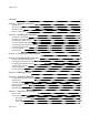
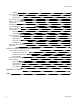
SimplyVAV Co n ten ts Contents 3 Section 1: About the controllers 5 Specifications Accessories and replacement parts Available models Safety considerations 7 11 12 13 Section 2: Installing the controllers 15 Setting the rotation limits Mounting on a VAV terminal box Connecting an airflow sensor Connecting inputs and outputs Connecting room temperature sensors Connecting a DAT sensor Connecting power Maintenance 16 17 18 18 19 20 21 22 Section 3: Changing the room setpoint 23 Section 4: Configu
SimplyVAV Standby Space setpoints Types of setpoints Setpoint limits PID control loops Airflow setpoints sequence Changeover Discharge Air Temperature (DAT) limiting System diagnostics Damper operation Fan operation Series Fan Parallel Fan Reheat sequence Modulating reheat Staged reheat Time proportioned reheat Floating reheat Balancing airflow sequence Dual duct Section 8: System integration and networking Connecting to an MS/TP network Connections and wiring End of line termination switches Network bulb
SimplyVAV Section 1: About the controlle rs This section provides a description of the SimplyVAV series of controllers. It also introduces safety information. Review this material before selecting, installing, or operating the controllers. The SimplyVAV series of controllers are an easy and unique approach to operating a wide variety of VAV terminal units.
Section 1: About the controllers SimplyVAV BAC-8005 and BAC-8205 Models BAC-8005 and BAC-8205 are supplied with inputs, outputs, and sequences of operation for the following functions.
SimplyVAV Specifications Section 1: About the controllers SimplyVAV specifications are subject to change without notice. Inputs and outputs All inputs and outputs are factory programmed and application specific. No field configuration is required. For details on input and output connections, see the topic Application drawings on page 49. For a detailed listing of input and output objects, see the topic BACnet objects on page 77. Analog inputs Analog inputs represent BACnet analog input.
Section 1: About the controllers SimplyVAV Connector Screw terminals for wire size 12-26 AWG Output range Maximum switching 24 Volts AC 1 ampere per external output, 3 amperes total Communications—BACnet MS/TP EIA–485 operating at rates up to 76.8 kilobaud. Removable screw terminal block. Wire size 12-26 AWG Switch selected end of line termination Memory Programs and program parameters are stored in nonvolatile memory.
SimplyVAV Section 1: About the controllers Regulatory UL 916 Energy Management Equipment BACnet Testing Laboratory listed as an application specific controller (ASC). CE compliant SASO PCP Registration KSA R-103263 FCC Class B, Part 15, Subpart B and complies with Canadian ICES-003 Class B This device complies with part 15 of the FCC Rules.
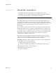
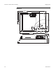
Section 1: About the controllers SimplyVAV Dimensions 6.53 in. 166 mm 4.89 in. 124 mm ON CTS 1 2 4.25 in. 108 mm 0.77 in. 19 mm 6.00 in. 152 mm 2.14 in. 54 mm 1.92 in.
SimplyVAV Accessories and replacement parts Section 1: About the controllers The following accessories and replacement parts are available from KMC Controls, Inc.
Section 1: About the controllers Available models 12 SimplyVAV The following is a list of SimplyVAV available models.
SimplyVAV Section 1: About the controllers Safety considerations KMC Controls assumes the responsibility for providing you a safe product and safety guidelines during its use. Safety means protection to all individuals who install, operate, and service the equipment as well as protection of the equipment itself. To promote safety, we use hazard alert labeling in this manual. Follow the associated guidelines to avoid hazards. Danger Danger represents the most severe hazard alert.
Section 1: About the controllers 14 SimplyVAV Revision E
SimplyVAV Section 2: I n s t al l i n g t h e c o n t r o l l e r s This section provides important instructions and guidelines for installing the SimplyVAV controllers. Carefully review this information before installing the controller. Installing SimplyVAV includes the following topics that are covered in this section.
Section 2: Installing the controllers Setting the rotation limits SimplyVAV SimplyVAV controllers are manufactured for a damper that rotates 90 degrees from open to close. If the VAV damper is not a 90 degree damper, set the rotation limits to 45 or 60 degrees before mounting the controller. Caution Before setting the rotation limits on the controller, refer to the damper position specifications in the VAV control box to which the controller will be attached.
SimplyVAV Section 2: Installing the controllers Mounting on a VAV terminal box Mount the controller inside of a metal enclosure. To maintain RF emissions specifications, use either shielded connecting cables or enclose all cables in conduit. Mount the controller directly over the damper shaft. A minimum shaft length of 2.0 inch (51 mm) is required. Note: SimplyVAV controllers are designed to directly mount to 3/8 to 5/8 inch (9.5 to 16 mm) round or 3/8 to 7/16 inch (9.5 to 11 mm) square damper shafts.
Section 2: Installing the controllers Connecting an airflow sensor SimplyVAV An airflow sensor is incorporated as one of the inputs to the controller. Remove the plugs and connect the tubing from the pitot assembly to the airflow sensor inputs next to the drive hub.
SimplyVAV Connecting room temperature sensors Section 2: Installing the controllers Connect any of the following sensors to the RJ-45 thermostat and sensor jack. The controller automatically detects the type of sensor. No programming or configuration is required. STE-6010 STE-8001 STE-6014 STE-8201 STE-6017 Connect the controller to sensors with standard Ethernet cables up to 75 feet long. See the installation guide supplied with the sensors for sensor installation instructions.
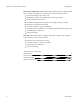
Section 2: Installing the controllers Connecting a DAT sensor SimplyVAV The Discharge Air Temperature sensor is required for automatic changeover and for VAV terminal units with reheat. Illustration 2–5 Discharge air temperature sensor location DAT sensor Changeover only DAT sensor Prefered location Connect a 10 kΩ, Type 3 thermistor temperature probe to the discharge air temperature input. The input includes the internal pull-up resistor. An STE-1401 sensor is suitable for this application.
SimplyVAV Connecting power Section 2: Installing the controllers The controllers require a 24 volt, AC power source. Use the following guidelines when choosing and wiring transformers to the controller. Use a Class–2 transformer of the appropriate size to supply power to the controller. KMC Controls recommends powering only one controller from each transformer. Do not run 24 volt, AC power from within an enclosure to external controllers.
Section 2: Installing the controllers Maintenance 22 SimplyVAV SimplyVAV controllers require no routine maintenance. If necessary, clean with a damp cloth and mild soap.
SimplyVAV Section 3: C h an g i n g t h e r o o m s e t p o i n t This section covers topics for the end user in a facility. Changing the SimplyVAV user functions with an STE-8001 or STE-8201 are limited to changing the active setpoints in a room. The setpoints are entered or changed using the buttons and display on the front of the sensor. Quick start to changing setpoints 1. Press any button to begin changing setpoints. 2. If required, enter Password 1. 3.
Section 3: Changing the room setpoint SimplyVAV Changing room setpoints (continued) Procedure Steps 2 1. Press any button. The display changes to PSW1. 2. Press the or buttons to change the first digit. 3. Press the button to select the next digit. Repeat for all four digits. Enter Password 1. STE display PSW1 OOOO Set Point Note: If Password 1 has not previously been entered, the display will change to the occupied cooling setpoint display after Step 1. 3 Set the active cooling setpoint. 1.
SimplyVAV Section 4: Configuring the controlle rs This topics in this section are advanced topics for control technicians and engineers. The configuration functions that are accessible through an STE-8000 series sensor are all of the values and settings that are entered during the installation and commissioning of a VAV terminal unit. Typically, these functions do not change after the installation and commissioning process.
Section 4: Configuring the controllers Getting started with configuration SimplyVAV For access to the configuration functions you will need Password 2. If the controller has not been previously set up, no password is required. A new Password 2 can be entered or changed in the advance functions. See the topic Advanced options on page 37. Enter the configuration mode Procedure Detailed steps 1 1. Start at the temperature display. Starting display 2. Press the l l 2 Enter Password 2.
SimplyVAV Section 4: Configuring the controllers Entering system temperature setpoints and limits The system temperature setpoints set the operational parameters and limits for the VAV terminal unit. The temperature setpoints include the following items.
Section 4: Configuring the controllers SimplyVAV Procedure to set the temperature setpoints (continued) Procedure Detailed steps 3 This setpoint limits the lowest temperature that a user can enter as the active setpoint. Set the minimum cooling setpoint. 1. Press the or buttons to set the minimum cooling setpoint. The setpoint will change in 0.5° increments. 2. Press the button to save the setpoint and advance to the next function.
SimplyVAV Section 4: Configuring the controllers Procedure to set the temperature setpoints (continued) Procedure Detailed steps 6 This setpoint is used as the active setpoint when the space is occupied. Set the occupied heating setpoint. 1. Press the or buttons to set the occupied heating setpoint. The setpoint will change in 0.5° increments. 2. Press the button to save the setpoint and advance to the next function.
Section 4: Configuring the controllers SimplyVAV Procedure to set the temperature setpoints (continued) Procedure Detailed steps 10 Set the minimum The minimum allowable temperature value between the cooling and heating setpoints. temperature differential setpoint. STE display 1. Press the or buttons to set the differential setpoint. The setpoint will change in 1° increments. 2. Press the button to save the setpoint and advance to the next function.
SimplyVAV Section 4: Configuring the controllers Configuring the VAV Box options The box options set the controller for the specific mechanical installation of the VAV terminal unit. The box options include the following items. The K-factor for the VAV terminal unit. If the K-factor is not available, see the topic K-factors on page 83.
Section 4: Configuring the controllers SimplyVAV Procedure to set the box functions (continued) Procedure Detailed steps 3 The K-factor is supplied by the manufacturer of the VAV terminal unit. Typically it is on the label with the unit airflow information. Set the primary VAV terminal unit K-factor. 1. Press the or buttons to set the primary K-factor. 2. Press the button to save the entry and advance to the next function.
SimplyVAV Section 4: Configuring the controllers Procedure to set the box functions (continued) Procedure Detailed steps 6 1. Press the or buttons to choose one of the following fan options. Set the fan option. STE display FAN Not used in all models. None—No fan is connected to the controller. NONE Series —The VAV unit includes a series fan. Parallel—The VAV unit includes a parallel fan. 2. Press the button to save the fan option and advance to the next function.
Section 4: Configuring the controllers Set the airflow setpoints SimplyVAV The airflow setpoints set the airflow limits for the VAV terminal unit. Airflow heating and cooling minimum and maximum limits Auxiliary flow setpoint (optional) Minimum and maximum fan speeds (optional) Setting the airflow setpoints requires entering Password 2 which is described in the topic Getting started with configuration on page 26.
SimplyVAV Section 4: Configuring the controllers Procedure to set the airflow setpoints (continued) Procedure Detailed steps 2 1. From the CNFG display, press the or buttons to show the CNFG display. CNFG 2. Press the button to select the CNFG options. The display changes to STPT. STPT Select the flow setpoint display. Set Point 3. Press the or buttons to change the display to FLOW. STE display FLOW 4. Press the button to select FLOW. The display changes to MNCL. Set Point 3 1.
Section 4: Configuring the controllers SimplyVAV Procedure to set the airflow setpoints (continued) Procedure 7 Detailed steps STE display or buttons to set the maximum Set the heating maximum 1. Press the limit for heating airflow. The setpoint will airflow limit. change in 1 CFM increments. 2. Press the button to save the setpoint and advance to the next function. Set Point 8 Set the minimum limit for fan speed. Not used for all models. 9 Set the maximum limit for fan speed.
SimplyVAV Section 4: Configuring the controllers Advanced options The advanced options set up passwords and special features in the controller. Establish or change Password 1 and Password 2 Set timers for standby and override (optional) Enable automatic occupancy (optional) Enable discharge air temperature control (optional) Calibrate the sensor Setting the advance options requires entering Password 2 which is described in the topic Getting started with configuration on page 26.
Section 4: Configuring the controllers SimplyVAV Procedure to set the advanced options (continued) Procedure Steps 3 Note: Entering four zeros (0000) removes the password. Change Password 1. STE display 1. Press the or buttons to change the first digit. 2. Press the button to select the next digit. Repeat for all four digits. 3. When the button is pressed for the last digit, the new password is saved and the display advances. PSW1 OOOO Set Point Set Point 4 Change Password 2.
SimplyVAV Section 4: Configuring the controllers Procedure to set the advanced options (continued) Procedure Steps 8 1. Press the or buttons to enable or disable discharge air temperature limiting. 2. Press the button to save the setpoint and advance to the next function. Set the automatic occupancy mode. STE display AUMD Set Point Requires a discharge air temperature sensor.
Section 4: Configuring the controllers Restore Application SimplyVAV Choose the RSTR function to reset the SimplyVAV controller to the original configuration and settings. Use it also to change the units of measure to display on a SimplyVAV sensor. There are two versions of the application program in the controller. The Metric version displays temperature in Celsius and uses metric values for units of measure.
SimplyVAV Section 4: Configuring the controllers Procedure to restore application (continued) Procedure 2 Detailed steps STE display or Select the restore settings 1. From the CNFG display, press the buttons to show the CNFG display. display. 2. Press the button to select the CNFG options. The display changes to STPT. Set Point 3. Press the or buttons to change the display to RSTR.
Section 4: Configuring the controllers 42 SimplyVAV Revision E
SimplyVAV Section 5: B al an c i n g ai r f l o w Topics in this section are for control technicians or engineers who will be balancing the airflow in the controllers. The airflow balancing procedure described in this section requires the following items. A flow hood or other accurate method to measure airflow. An STE-8001 or STE-8201 wall sensor. If the system does not include one of these sensors, temporarily disconnect the installed sensor and connect an STE-8001 as a service tool.
Section 5: Balancing airflow Table 5–1 SimplyVAV The airflow balancing procedure Procedure Steps 1 1. Start at the temperature display. Starting display STE display 2. Press the l l 2 Select the CNFG display. and buttons together. If Password 2 is not required, the display changes to CNFG. If required, enter Password 2. The display changes to CNFG when Password 2 is correct. 1. From the CNFG display, press the or buttons to advance to COMM and the BLNC display.
SimplyVAV Section 5: Balancing airflow The airflow balancing procedure (continued) Procedure Steps 3 The display begins flashing PMAX and also displays the actual airflow at the bottom. Measure and enter the actual maximum primary airflow STE display Note: The airflow will attempt to stabilize on the highest value for either the cooling or heating maximum airflow even if only one mode is operational.
Section 5: Balancing airflow SimplyVAV The airflow balancing procedure (continued) Procedure Steps 5 1. Press the or buttons to select one of the following: Advance or exit STE display SEC to balance the secondary VAV for dual duct systems. Choosing SEC advances to the SMAX display. This is available only on dual duct models. PRI SEC BACK to choose another commissioning function EXIT to return to the temperature display. 2.
SimplyVAV Section 5: Balancing airflow The airflow balancing procedure (continued) Procedure Steps 7 The display begins flashing SMIN and also displays the actual airflow at the bottom. Measure and enter the actual minimum secondary airflow STE display Note: The airflow displayed by the STE-8000 in this step is the actual, uncorrected airflow. 1. Wait for the minimum airflow value to stabilize. 2. With a flow hood, measure the actual airflow. SMIN OO 3.
Section 5: Balancing airflow 48 SimplyVAV Revision E
SimplyVAV Section 6: A p p l i c at i o n d r aw i n g s This section covers the drawings, materials, and instructions for specific VAV applications. Each SimplyVAV model is designed for a specific set of applications. The following topics are for control technicians and engineers that will plan for and install controllers for SimplyVAV applications. Submittal sheets for all of these applications are available from the Resources page at www.SimplyVAV.com.
Section 6: Application drawings Cooling or heating without reheat SimplyVAV The BAC-8001 is configured for single-duct cooling VAV control without reheat. Connect the controller as shown in the illustration Cooling or heating application drawing on page 50. A BAC-8005 or BAC-8205 may also be used for this application. For cooling and heating, a duct temperature sensor is required for Discharge Air Temperature limiting and automatic changeover.
SimplyVAV Section 6: Application drawings Staged reheat This application is for BAC-8005 or BAC-8205 controllers. The controllers are configured to switch reheat units that are controlled with 24 volts AC. Reheat units with up to three stages of reheat can be controlled by these controllers. For one-stage or electric reheat or hot water reheat with an on/off valve, use only output terminal BO6. For two-stage reheat use output terminals BO6 and BO7.
Section 6: Application drawings Modulating reheat SimplyVAV This application is for a BAC-8005 or BAC-8205 controller. The modulating option for reheat can control either an electric reheat unit with an analog input or a modulating hot water valve. The analog reheat output at output terminal AO3 varies between 0 and 10 volts DC. For cooling and heating, a duct temperature sensor is required for Discharge Air Temperature limiting and automatic changeover.
SimplyVAV Section 6: Application drawings Time proportional reheat This application is for a BAC-8005 or BAC-8205 controller. The time proportional reheat option is typically used in hydronic systems with a hot water reheat coil and a wax top control valve.The reheat output is a triac that can switch up to 1 ampere at 24 volts AC. For cooling and heating, a duct temperature sensor is required for Discharge Air Temperature limiting and automatic changeover.
Section 6: Application drawings Floating reheat SimplyVAV This application is for a BAC-8005 or BAC-8205 controller. Use the floating reheat option in hydronic systems that are controlled by an actuator with tristate inputs. The reheat outputs are triacs that can switch up to 1 ampere at 24 volts AC. For cooling and heating, a duct temperature sensor is required for Discharge Air Temperature limiting and automatic changeover.
SimplyVAV Dual-duct application Section 6: Application drawings This application is for a BAC-8007 controller. The controller is configured for dual-duct operation. Dual-duct VAV requires a TSP-8001 actuator to be used with the BC-8007 as shown in the illustration Dual-duct wiring diagram on page 55. Submittal sheets for several variations of this application are available from the Resources page at www.SimplyVAV.com.
Section 6: Application drawings 56 SimplyVAV Revision E
SimplyVAV Section 7: Se q u e n c e s o f o p e r at i o n Topics in this section cover the sequences of operation for the SimplyVAV controllers. These are advanced topics for control technicians and engineers. These sequences of operation are descriptions of each major component of the SimplyVAV programming. They are provided as an aid to understanding on how the controllers operate. This section covers the following sequences of operation.
Section 7: Sequences of operation Input sources SimplyVAV The SimplyVAV controllers require specific sensors to measure room temperature, airflow, and discharge air temperature. All sensors are automatically detected and the programming is automatically set up for the sensors.
SimplyVAV Section 7: Sequences of operation along with the K-factor of the VAV terminal unit are used to calculate the airflow through the VAV unit. Occupancy sequence A SimplyVAV controller is designed to operate as a stand-alone controller and determine occupancy based only on the availability of primary airflow and motion in the zone. The controller can be in any one of the following occupancy states.
Section 7: Sequences of operation SimplyVAV defined as two movements detected within 5 minutes. The controller will change back to Standby after a lack a lack of motion for the period specified by the variable Standby Time. Standby mode is not valid for controllers without a motion sensor, unless commanded by a building management system. Space setpoints There are four temperature setpoints each for heating and cooling for a total of eight setpoints.
SimplyVAV Section 7: Sequences of operation Standby setpoint—The standby setpoint is used when the controller is in the standby state. It is a value calculated from the occupied setpoint and the value of Standby Offset. The standby offset value is entered by the controls technician during controller setup and system commissioning. See the topic Occupancy sequence on page 59.
Section 7: Sequences of operation SimplyVAV If there is a call for reheat to maintain room temperature, the primary airflow is set to the value of Auxiliary Flow. Warm Air Available In the heating mode, as the Heating Loop increases from 0% to 100%, Primary Airflow Setpoint is proportionally calculated between Minimum Heating Airflow and Maximum Heating Airflow. See also the topics, Changeover on page 62 and Input sources on page 58.
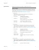
SimplyVAV Section 7: Sequences of operation Illustration 7–1 DAT limiting operation ROOM TMP+15° (Max 90°F) DAT loop ROOM TMP 100% 50% HTG SPAN 0% HTG SP If DAT Limiting is enabled, and a DAT sensor is not connected, the controller will lockout reheat control only in the cooling mode. The unit will operate this way until a DAT sensor is detected or until the unit is commanded to control to the Active Heating Setpoint by a supervisory BMS.
Section 7: Sequences of operation System diagnostics SimplyVAV The controller programming includes four system diagnostic indicators in the form of BACnet value objects. Need for higher static pressure Need for cooler supply air Need for warmer supply air Need AHU start These diagnostic indicators or flags are monitored by other BACnet devices connected to the same building automation system as the controller. How the indicators are used is beyond the scope of these instructions.
SimplyVAV Section 7: Sequences of operation Damper operation Damper movement is determined by comparing the actual airflow reading to the airflow setpoints. If the actual airflow is within 5% of the setpoint, no damper action is initiated. Once within the 5% deadband, the actual airflow must be outside a 7% deadband before damper position changes. Fan operation The SimplyVAV controllers support both series and parallel fan powered VAV units.
Section 7: Sequences of operation SimplyVAV Parallel Fan If the controller is configured for a parallel fan, any time the Occupancy mode of the controller is set to either Occupied or Standby and there is a call for heat, the fan runs continuously. The fan starts when the Heating loop is greater than 5% and stops when the Heating loop is less than 1%. When the unit Occupancy state is Unoccupied, the fan starts and runs at minimum speed only on a call for heating.
SimplyVAV Section 7: Sequences of operation reheat, the reheat output is modulated over the span of the Reheat loop. If the Reheat loop is less than 10%, the reheat output remains at zero. The reheat is set to zero if the Cooling loop is active. See the topic Modulating reheat on page 52 for an application drawing.
Section 7: Sequences of operation SimplyVAV loop is at 50%, the reheat output is On for 5 seconds and Off for 5 seconds. If the Reheat loop is less than 10%, the reheat output remains at zero. See the topic Time proportional reheat on page 53 for an application drawing.
SimplyVAV Balancing airflow sequence Section 7: Sequences of operation Balancing airflow is the process of calibrating the internal airflow sensor to a known standard. In the field, airflow is measured with an airflow hood or other measuring instrument and then compared to the airflow measurements from the sensor in the controller. The balancing process uses an STE-8001 or STE-8201 as the technicians setup tool for initiating the balancing sequence and entering actual flow measurements.
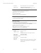
Section 7: Sequences of operation SimplyVAV Illustration 7–7 Dual duct sequence Airflow increase Max.
SimplyVAV Section 8: Sy s t e m i n t e g r at i o n an d n e t w o r ki n g Topics in this section cover integrating the controllers into a building automation network. These are advanced reference topics for control technicians and engineers. The controllers can be installed as standalone controllers or they can be connected to a BACnet MS/TP network.
Section 8: System integration and networking Connecting to an MS/TP network SimplyVAV SimplyVAV controllers are BACnet MS/TP compliant controllers. Connect them only to a BACnet MS/TP network. To enter the BACnet device instance, MAC address, and network baud, see the topic Setting up network communications on page 75.
SimplyVAV Section 8: System integration and networking Connect no more than 128 addressable BACnet devices to one MS/TP network. The devices can be any mix of controllers or routers. To prevent network traffic bottlenecks, limit the MS/TP network size to 60 controllers. Use twisted pair, shielded cable with capacitance of no more than 51 picofarads per foot for all network wiring. Belden cable model #82760 meets the cable requirements. Connect the -A terminal in parallel with all other - terminals.
Section 8: System integration and networking SimplyVAV Bulbs are open If one or both bulbs are open—as tested with an ohm meter—it indicates the voltage or current on the network exceeded safe levels. Correct the conditions and replace the bulbs. Bulbs not inserted correctly One lead from one or both of the bulbs are not inserted into the socket.
SimplyVAV Section 8: System integration and networking Setting up network communications Table 8–1 Set the network communication settings before placing a controller on the network. Setting network settings requires entering Password 2 which is described in the topic Getting started with configuration on page 26. Procedure to set up network communications Procedure Detailed steps 1 1. Start at the temperature display. Starting display STE display 2.
Section 8: System integration and networking SimplyVAV Procedure to set up network communications (continued) Procedure Detailed steps 5 1. Press the Enter the baud 2. Press the STE display or Set Point buttons to select a new baud. button is save the selected baud. The display returns to COMM. 6 Advance or exit 1. Press the or following: buttons to select one of the BAUD 384OO COMM BLNC or CNFG options EXIT to return to the temperature display. 2.
SimplyVAV Section 8: System integration and networking BACnet objects The SimplyVAV controllers are BACnet Application Specific Controller (ASC) that are composed of standard BACnet objects. This section lists the objects that are likely to be monitored by a standard BACnet operator workstation to verify system operation. Caution Changing the configuration of any object may result in unpredictable operation of a controller and damage to equipment that is under control of a SimplyVAV controller.
Section 8: System integration and networking SimplyVAV Output objects (continued) Output Name Description Units AO4 FAN SPEED Fan Speed 0_100% BO1 DAMPER CW Damper Clockwise BO2 DAMPER CCW Damper Counter Clockwise BO5 FAN Fan BO6 HT STAGE 1 Heating Stage 1 BO7 HT STAGE 2 Heating Stage 2 BO8 HT STAGE 3 Heating Stage3 Value objects BACnet value objects represent setpoints or other operational conditions in the controller. Note: Not all objects are present in every model.
SimplyVAV Section 8: System integration and networking Analog value objects (continued) Revision E Object Name Description AV14 MAX COOL FLOW Maximum Cooling Flow AV15 MIN HEAT FLOW Minimum Heating Flow AV16 MAX HEAT FLOW Maximum Heating Flow AV17 AUXILLARY FLOW Auxillary Flow AV18 PRI K FACT Primary K Factor AV19 PRI CORR SLOPE Primary Correction Slope AV20 PRI CORR OFFST Primary Correction Offset AV21 PRI LO FLOW CORR Primary Low Flow Correction AV22 PRI FLOW STPT Primary F
Section 8: System integration and networking Table 8–5 SimplyVAV Binary value objcts Object Name Description BV1 NEED AHU Need For AHU BV2 NEED COLDER SPLY Need For Colder Air Supply BV3 NEED MORE STATIC Need For AHU BV4 LOCAL OVRD Local Override Mode BV5 MOTION OVRD Motion Override Mode BV6 MOTION SENSOR Motion Sensor (Wall Stat) BV7 NEED HOTTER SPLY Need For Hotter Air Supply BV8 CHANGE OVER MODE SAT Changeover Mode BV9 DAT LIMITING Discharge Air Temp Limiting BV10 CLOCKW
SimplyVAV Section 8: System integration and networking PID control loop objects (continued) Loop Revision E Name Description LOOP2 HT LOOP Heating Loop LOOP3 DAT Loop Discharge Air Temp Loop 81
Section 8: System integration and networking 82 SimplyVAV Revision E
SimplyVAV Appendix A: K-factors A p p e n d i x A : K - f ac t o r s To set up a VAV controller, a K-factor must be entered into the controller. Typically, this is part of the airflow chart that the manufacturer places on the VAV unit. If this information is missing and not available from the manufacturer, use the K-factor in the following chart.
Appendix A: K-factors 84 SimplyVAV Revision E
SimplyVAV Inde x A accessories 11 actuator mounting 17 rotation limits 16 shaft size 7 specifications 7 speed 7 airflow balancing 43 maximum limit 34 minimum limit 34 sensor 18 setting limits 34 applications 49 cooling only without reheat 50 cooling/heating without reheat 50 dual duct 55 floating reheat 54 modulating reheat 52 staged reheat 51 three-stage reheat 51 time proportional reheat 53 automatic occupancy enabling 37 sequence 59 auxillary flow sequence 61 setting 34 B BAC-8001 cooling only 50 cooli
Index fans configuration 31 parallel sequence 65 series sequence 65 setting speed 34 speed sequence 65 with floating reheat 54 with modulating reheat 52 with staged reheat 51 with time proportional reheat 53 floating reheat 54 I inputs as BACnet objects 77 connecting 18 DAT sensor 20 room sensors 19 specifications 7 installing the controller 15 K K-factor setting 31 unknown 83 M MAC address 75 maintenance 22 Metric display 40 models 12 modulating reheat 52 motion sensing sequence 59 mounting 17 MS/TP wi
SimplyVAV room sensors 19 sequence 58 sequences of operation 57 airflow setpoints 61 balancing 69 changeover 62 damper 65 DAT limiting 62 dual duct 69 fans 65 input sources 58 motion detection 59 occupancy 59 PID loops 61 sensors 58 setpoints 60 standby 59 system diagnostics 64 unoccupied 59 series fan 65 configuration 31 sequence 65 setpoints limits sequence 60 room temperature sequence 60 sequence 60 setting changeover 27 limits 27 occupied 27 room 23 standby 27 shaft size for actuator 7 specifications 7
Index 88 SimplyVAV Revision E