
Install Instructions

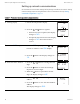

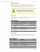

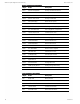
Table Of Contents
- Contents
- Section 1: About the controllers
- Section 2: Installing the controllers
- Section 3: Changing the room setpoint
- Section 4: Configuring the controllers
- Section 5: Balancing airflow
- Section 6: Application drawings
- Section 7: Sequences of operation
- Section 8: System integration and networking
- Appendix A: K-factors
- Index

Object Name Description
AV21 PRI LO FLOW CORR Primary Low Flow Correction
AV22 PRI FLOW STPT Primary Flow Setpoint
AV23 PRI RAW FLOW Primary Raw Flow
AV24 PRI ACTUAL FLOW Primary Actual Flow
AV32 MIN FAN SPEED Minimum Fan Speed
AV33 MAX FAN SPEED Maximum Fan Speed
AV36 DAT STPT Discharge Air Temp Setpoint
AV37 SAT CHANGEOVER SAT Changeover Temperature
AV38 LOCAL OVRD TIME Local Override Timer
AV39 STANDBY TIME Standby Timer (motion)
AV40 STANDBY TRIGGER Standby Trigger
AV43 MEASURED MAX Measured Maximum
AV44 MEASURED MIN Measured Minimum
AV45 PRI SAVE MIN FLO Primary Saved Minimum Airflow
AV47 DAT MAXIMUM Maximum DAT Setpoint
AV48 CW DMP POS CW Damper Position
AV49 CCW DMP POS CCW Damper Position
AV50 DAMPER POSITION Damper Position
AV51 ApplicationID
AV54 MOTOR PAUSE Analog Value #54
AV55 CHNG_OVER_DELAY Cooling Change Over Delay
AV56 LOW AUTO OCC Low Limit for Auto Occupy
Analog value objects (continued)
Object Name Description
BV1 NEED AHU Need For AHU
BV2 NEED COLDER SPLY Need For Colder Air Supply
BV3 NEED MORE STATIC Need For AHU
BV4 LOCAL OVRD Local Override Mode
BV5 MOTION OVRD Motion Override Mode
Table 8–5 Binary value objcts
Section 8: System integration and networking KMC Controls, Inc.
70 Revision G