
Install Instructions
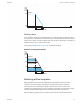
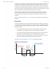

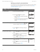


Table Of Contents
- Contents
- Section 1: About the controllers
- Section 2: Installing the controllers
- Section 3: Changing the room setpoint
- Section 4: Configuring the controllers
- Section 5: Balancing airflow
- Section 6: Application drawings
- Section 7: Sequences of operation
- Section 8: System integration and networking
- Appendix A: K-factors
- Index

At the start of the sequence, the controller drives the damper open until the airflow reaches
the highest value of either the cooling or heating maximum airflow setpoints. An airflow
measurement is made with an airflow hood and the actual airflow value is entered into the
controller. Once the actual airflow is entered, the controller drives the damper closed to the
lower value of either the cooling or heating minimum airflow. Another measurement is made
with the flow hood and that measurement is entered into the controller.
After the minimum airflow measurement is entered, the programming in the controller
calculates airflow correction factors which are used to adjust measurements from the
internal airflow sensor. Balancing is complete and the controller is returned to normal
operation.
See the topic Balancing airflow on page 40 for the procedure to balance the airflow with an
STE-8001.
Dual duct
A dual duct installation consists of separate primary heating and cooling ducts, both with
control dampers and airflow monitoring. For this type of installation a SimplyVAV BAC-8007
controls the cooling air (primary) damper and a TSP-8001 actuator controls the heating air
(secondary) damper.
l As the space temperature rises above the cooling setpoint, the primary airflow is
modulated from the Cooling Minimum flow to the Cooling Maximum Flow.
l As the space temperature falls below the heating setpoint, the secondary airflow is
modulated from the Heating Minimum flow to the Heating Maximum Flow.
l Between the heating and cooling setpoints, both the primary airflow and secondary
airflow are modulated to maintain the Dual Duct Minimum airflow.
See the topic, Dual-duct application on page 50 for an application drawing.
Illustration 7–7 Dual duct sequence
Max. cooling airflow
Airflow increase
Max heating airflow
Dual duct
minimum
airflow
Room temp increase
HTG SPAN CLG SPAN
HTG SP CLG SP
MIN
CLG
CFM
MIN
HTG
CFM
Section 7: Sequences of operation KMC Controls, Inc.
62 Revision G