
Install Instructions
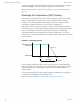
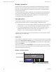
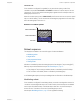
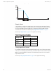
Table Of Contents
- Contents
- Section 1: About the controllers
- Section 2: Installing the controllers
- Section 3: Changing the room setpoint
- Section 4: Configuring the controllers
- Section 5: Balancing airflow
- Section 6: Application drawings
- Section 7: Sequences of operation
- Section 8: System integration and networking
- Appendix A: K-factors
- Index

70°F. If the user lowers the Occupied Cooling setpoint to 71°F, the controller recalculates
the Occupied Heating setpoint and changes it to 67°F.
PID control loops
A PID control loop calculates an error value from the difference between the measured room
temperature and the active setpoint. The error value is expressed as a percentage and is
typically used in a BAS controller to control the state of an output. When the difference
between the setpoint and room temperature is large, the error is large. As the system
reduces the difference between the setpoint and space temperature, the error becomes
smaller.
The SimplyVAV controllers use up to three PID loops.
l The heating PID loop.
l The cooling PID loop.
l The discharge air temperature (DAT) loop.
For SimplyVAV controllers, the output of either the cooling and heating PID loop is used to
calculate the position of the damper. If present, the DAT input and DAT loop controls the
Reheat loop.
The PID loops in the SimplyVAV controllers are standard BACnetobjects and are described
in the topic BACnet objects on page 68.
Airflow setpoints sequence
Airflow Setpoint is calculated based on the demand for cooling or heating depending on
whether the Cooling loop or Heating loop is greater than zero.
If no room sensor is connected to the controller, the controller uses the Minimum Cooling
Airflow setpoint to maintain airflow.
Cool Air Sequence
As the Cooling loop increases from 0% to 100%, Primary Airflow
Setpoint is proportionally calculated between Minimum Cooling Airflow and Maximum
Cooling Airflow.
If there is a call for reheat to maintain room temperature, the primary airflow is set to the
value of Auxiliary Flow.
Warm Air Available
In the heating mode, as the Heating Loop increases from 0% to 100%,
Primary Airflow Setpoint is proportionally calculated between Minimum Heating Airflow and
Maximum Heating Airflow.
See also the topics, Changeover on page 55 and Input sources on page 52.
Changeover
The Discharge Air Temperature input is used by the controller to determine the type of air
that is being supplied by the AHU. The sensor is required for applications that require
automatic change over between cooling and heating.
When the Heating loop is inactive, the Discharge Air Temperature input is compared to the
SAT Changeover Temp. If the Discharge Air Temperature is below the SAT Changeover
Temp minus 2°, the SAT Changeover Mode is set to COOL. If the Discharge Air
SimplyVAV Section 7: Sequences of operation
Revision G 55