
Install Instructions
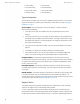
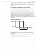
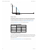
Table Of Contents
- Contents
- Section 1: About the controllers
- Section 2: Installing the controllers
- Section 3: Changing the room setpoint
- Section 4: Configuring the controllers
- Section 5: Balancing airflow
- Section 6: Application drawings
- Section 7: Sequences of operation
- Section 8: System integration and networking
- Appendix A: K-factors
- Index

Damper operation
Damper movement is determined by comparing the actual airflow reading to the airflow
setpoints. If the actual airflow is within 5% of the setpoint, no damper action is initiated.
Once within the 5% deadband, the actual airflow must be outside a 7% deadband before
damper position changes.
To improve stability near setpoint, the damper motor is pulsed when the actual flow rate is
within 15% of the requested flow rate. The pulse rate is 5 seconds and the duty cycle is
controlled by analog variable MOTOR PAUSE. In addition, the motor will pause for 10
seconds before the damper changes direction.
Fan operation
The SimplyVAV controllers support both series and parallel fan powered VAV units. For
either type of fan operation, the fan is controlled through the following terminals.
l A binary output triac controls a 24-volt fan starting circuit. See the topic Configuring the
VAV Box options on page 29 for the procedure to configure the controller for a fan.
l A 0-10 volt DC analog output controls the speed of the fan. The output controls fan
speed at either Min Fan Speed or Max Fan Speed. See the topic Set the airflow
setpoints on page 32 for the procedure to set the fan speeds.
If the VAV unit is not configured for a fan, the two outputs are not used and remain inactive
regardless of the occupancy state.
Series Fan
If the controller is configured for a series fan, any time the Occupancy mode of the controller
is set to either OCCUPIED or STANDBY, the fan runs continuously. The fan speed is set to
Maximum Fan Speed when the state is OCCUPIED and set to Minimum Fan Speed when
the state is STANDBY.
When the Occupancy state is UNOCCUPIED, the fan starts and runs at minimum speed
only on a call for heating. The fan starts when the Heating loop is greater than 5% and stops
when the Heating loop is less than 1%.
Illustration 7–2 Series fan operation
UNOCCUPIED/
STANDBY
STANDBY
MAX FAN SPEED
MIN FAN SPEED
FAN OFF
OCCUPIED
HTG SP ROOM TEMP INCREASE
Section 7: Sequences of operation KMC Controls, Inc.
58 Revision G