
Install Instructions


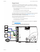

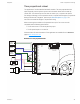
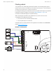
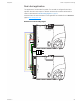
Table Of Contents
- Contents
- Section 1: About the controllers
- Section 2: Installing the controllers
- Section 3: Changing the room setpoint
- Section 4: Configuring the controllers
- Section 5: Balancing airflow
- Section 6: Application drawings
- Section 7: Sequences of operation
- Section 8: System integration and networking
- Appendix A: K-factors
- Index

Modulating reheat
This application is for a BAC-8005 or BAC-8205 controller. The modulating option for reheat
can control either an electric reheat unit with an analog input or a modulating hot water
valve. The analog reheat output at output terminal AO3 varies between 0 and 10 volts DC.
For cooling and heating, a duct temperature sensor is required for Discharge Air Temperature
limiting and automatic changeover. See the topic Advanced options on page 35 for
instructions to enable Discharge Air Temperature limiting.
When connecting the controller to a fan powered VAV unit, the fan circuits must be
compatible with the following specifications.
l The fan start circuit is a 24 volt AC pilot duty output.
l The fan speed output is 0-10 volts DC.
Submittal sheets for several variations of this application are available from the Resources
page at www.SimplyVAV.com.
Illustration 6–3 Modulating reheat
ON CTS
1 2
COMM
READY
AI1
AI5
GND
AO4
AO3
SC
BO8
BO5
BO6
SC
BO7
24VAC
AI6
GND
AI7
T-STAT/
SENSOR
-A
+B
S
EOL
BACnet MS/TP
Fan
Speed
0-10 VDC
Duct
Temp
Sensor
Analog
Heat
24VAC
Fan start
24 VAC
Class 2
Section 6: Application drawings KMC Controls, Inc.
47 Revision G