SimplyVAV Application and Installation Guide Revision G
KMC Controls, Inc. ©2016, KMC Controls, Inc. SimplyVAV and the SimplyVAV logo are trademarks of KMC Controls, Inc. All rights reserved. No part of this publication may be reproduced, transmitted, transcribed, stored in a retrieval system, or translated into any language in any form by any means without the written permission of KMC Controls, Inc. Printed in U.S.A. The material in this manual is for information purposes only. The contents and the product it describes are subject to change without notice.
SimplyVAV Contents Co n te n ts Contents 3 Section 1: About the controllers Specifications Accessories and replacement parts Available models Safety considerations 5 7 10 10 12 Section 2: Installing the controllers Setting the rotation limits Mounting on a VAV terminal box Connecting an airflow sensor Connecting inputs and outputs Connecting room temperature sensors Connecting a DAT sensor Connecting power Maintenance 13 14 14 15 16 17 18 19 20 Section 3: Changing the room setpoint 21 Section 4:
Contents System diagnostic indicators Damper operation Fan operation Series Fan Parallel Fan Reheat sequence Modulating reheat Staged reheat Time proportioned reheat Floating reheat Balancing airflow sequence Dual duct KMC Controls, Inc.
SimplyVAV S e c t i o n 1: About the controllers This section provides a description of the SimplyVAV series of controllers. It also introduces safety information. Review this material before selecting, installing, or operating the controllers. The SimplyVAV series of controllers are an easy and unique approach to operating a wide variety of VAV terminal units.
Section 1: About the controllers KMC Controls, Inc.
SimplyVAV Section 1: About the controllers Specifications SimplyVAV specifications are subject to change without notice. Inputs and outputs All inputs and outputs are factory programmed and application specific. No field configuration is required. For details on input and output connections, see the topic Application drawings on page 44. For a detailed listing of input and output objects, see the topic BACnet objects on page 68. Analog inputs Analog inputs represent BACnet analog input.
Section 1: About the controllers KMC Controls, Inc. Communications—BACnet MS/TP l EIA–485 operating at rates up to 76.8 kilobaud. l Removable screw terminal block. l Wire size 12-26 AWG l Switch selected end of line termination Memory l Programs and program parameters are stored in nonvolatile memory. l Auto restart on power failure Air flow sensor features l l Configured as BACnet analog input object. CMOS differential pressure 0-2 inches of water (0-500 Pa) measurement range.
SimplyVAV Section 1: About the controllers Installation Supply voltage 24 volts AC, -15%, +20% 5 VA, 50/60 Hz Weight 13.2 ounces (376 grams) Case material Flame retardant plastic Environmental limits Operating 32 to 120° F (0 to 49° C) Shipping –40 to 140° F (–40 to 60° C) Humidity 5–93% relative humidity (non-condensing) Dimensions 6.53 in. 166 mm 4.89 in. 124 mm ON CTS 1 2 4.25 in. 108 mm 0.77 in. 19 mm 6.00 in. 152 mm 2.14 in. 54 mm 1.92 in.
Section 1: About the controllers KMC Controls, Inc. Accessories and replacement parts The following accessories and replacement parts are available from KMC Controls, Inc.
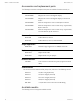
SimplyVAV Section 1: About the controllers Description Models BACnet ASC: VAV Cooling/Heating only, 40 in-lbs, 90 second actuator BAC-8001 BACnet ASC: VAV Fan and Reheat, 40 in-lbs, 90 second actuator BAC-8005 BACnet ASC: VAV Dual Duct, 40 in-lbs, 90 second actuator BAC-8007 BACnet ASC: VAV Fan and Reheat, True damper position, 40 in-lbs, BAC-8205 60 second actuator Revision G 11
Section 1: About the controllers KMC Controls, Inc. Safety considerations KMC Controls assumes the responsibility for providing you a safe product and safety guidelines during its use. Safety means protection to all individuals who install, operate, and service the equipment as well as protection of the equipment itself. To promote safety, we use hazard alert labeling in this manual. Follow the associated guidelines to avoid hazards. Danger Danger represents the most severe hazard alert.
SimplyVAV S e c t i o n 2: I n s t al l i n g t h e c o n t r o l l e r s This section provides important instructions and guidelines for installing the SimplyVAV controllers. Carefully review this information before installing the controller. Installing SimplyVAV includes the following topics that are covered in this section.
Section 2: Installing the controllers KMC Controls, Inc. Setting the rotation limits SimplyVAV controllers are manufactured for a damper that rotates 90 degrees from open to close. If the VAV damper is not a 90 degree damper, set the rotation limits to 45 or 60 degrees before mounting the controller. Caution Before setting the rotation limits on the controller, refer to the damper position specifications in the VAV control box to which the controller will be attached.
SimplyVAV Section 2: Installing the controllers Illustration 2–2 Controls and indicators Gear clutch button Status LEDs AI1 T-STAT/ SENSOR COMM READY ON CTS 1 2 GND BACnet MS/TP EOL S AO4 -A Mounting tab +B AO3 AI5 AI6 GND AI7 SC BO5 Mounting bushing BO6 Drive hub and V-bolt BO7 SC BO8 24VAC Mount the controller as follows: 1 Manually rotate the damper on the VAV box to the fully open position.
Section 2: Installing the controllers KMC Controls, Inc. Typically, airflow sensors are supplied by the manufacturer as part of the VAV terminal unit. If a sensor is needed, choose a sensor listed in the topic Accessories and replacement parts on page 10. Connecting inputs and outputs SimplyVAV series controllers have preconfigured inputs and outputs to support only the supplied programs and applications.
SimplyVAV Section 2: Installing the controllers Connecting room temperature sensors Connect any of the following sensors to the RJ-45 thermostat and sensor jack. The controller automatically detects the type of sensor. No programming or configuration is required. l STE-6010 l STE-8001 l STE-6014 l STE-8201 l STE-6017 Connect the controller to sensors with standard Ethernet cables up to 75 feet long. See the installation guide supplied with the sensors for sensor installation instructions.
Section 2: Installing the controllers KMC Controls, Inc. Connecting a DAT sensor The Discharge Air Temperature sensor is required for automatic changeover and for VAV terminal units with reheat. Illustration 2–5 Discharge air temperature sensor location DAT sensor Changeover only DAT sensor Prefered location Connect a 10 kΩ, Type 3 thermistor temperature probe to the discharge air temperature input. The input includes the internal pull-up resistor. An STE-1401 sensor is suitable for this application.
SimplyVAV Section 2: Installing the controllers Connecting power The controllers require a 24 volt, AC power source. Use the following guidelines when choosing and wiring transformers to the controller. l Use a Class–2 transformer of the appropriate size to supply power to the controller. l KMC Controls recommends powering only one controller from each transformer. l Do not run 24 volt, AC power from within an enclosure to external controllers.
Section 2: Installing the controllers KMC Controls, Inc. Maintenance SimplyVAV controllers require no routine maintenance. If necessary, clean with a damp cloth and mild soap.
SimplyVAV S e c t i o n 3: Ch an gi n g t h e r o o m s e t p o i n t This section covers topics for the end user in a facility. Changing the SimplyVAV user functions with an STE-8001 or STE-8201 are limited to changing the active setpoints in a room. The setpoints are entered or changed using the buttons and display on the front of the sensor. Quick start to changing setpoints 1. Press any button to begin changing setpoints. 2. If required, enter Password 1. 3. Press the up or down setpoint value.
Section 3: Changing the room setpoint KMC Controls, Inc. Changing room setpoints (continued) Procedure Steps STE display Note: If Password 1 has not previously been entered, the display will change to the occupied cooling setpoint display after Step 1. 3 Set the active cooling setpoint. 1. Press the or buttons to change the cooling setpoint temperature. The setpoint changes in increments of 0.5 degrees. 2. Press the Set Point 745 COOLING button to save the value.
SimplyVAV S e c t i o n 4: Co n f i gu r i n g t h e c o n t r o l l e r s This topics in this section are advanced topics for control technicians and engineers. The configuration functions that are accessible through an STE-8000 series sensor are all of the values and settings that are entered during the installation and commissioning of a VAV terminal unit. Typically, these functions do not change after the installation and commissioning process.
Section 4: Configuring the controllers KMC Controls, Inc. Getting started with configuration For access to the configuration functions you will need Password 2. l l If the controller has not been previously set up, no password is required. A new Password 2 can be entered or changed in the advance functions. See the topic Advanced options on page 35. Enter the configuration mode Procedure 1 Starting display Detailed steps STE display 1. Start at the temperature display. 72 12S1 2.
SimplyVAV Section 4: Configuring the controllers Entering system temperature setpoints and limits The system temperature setpoints set the operational parameters and limits for the VAV terminal unit. The temperature setpoints include the following items.
Section 4: Configuring the controllers KMC Controls, Inc. Procedure to set the temperature setpoints (continued) Procedure Detailed steps STE display 1. Press the or buttons to set the minimum cooling setpoint. The setpoint will change in 0.5° increments. 2. Press the button to save the setpoint and advance to the next function. Set Point 4 Set the maximum heating setpoint. This setpoint limits the highest temperature a user can enter as the active setpoint. 1.
SimplyVAV Section 4: Configuring the controllers Procedure to set the temperature setpoints (continued) Procedure 7 Set the unoccupied cooling setpoint. Detailed steps This setpoint is used as the active setpoint when the space is unoccupied. 1. Press the or buttons to set the unoccupied cooling setpoint. The setpoint will change in 0.5° increments. STE display UNCL 8OO 2. Press the button to save the setpoint and advance to the next function. Set Point 8 Set the unoccupied heating setpoint.
Section 4: Configuring the controllers KMC Controls, Inc. Procedure to set the temperature setpoints (continued) Procedure Detailed steps STE display 2. Press the button to save the setpoint and advance to the next function. Set Point 12 Select a new configuration function or exit. 1. Press the or following: buttons to select one of the l BOX, FLOW, ADVC, or RSTR options l BACK to choose another configuration STPT function. l EXIT to return to the temperature display. 2. Press the function.
SimplyVAV Section 4: Configuring the controllers Configuring the VAV Box options The box options set the controller for the specific mechanical installation of the VAV terminal unit. The box options include the following items. l The K-factor for the VAV terminal unit. If the K-factor is not available, see the topic Kfactors on page 72.
Section 4: Configuring the controllers KMC Controls, Inc. Procedure to set the box functions (continued) Procedure 3 Set the primary VAV terminal unit K-factor. Detailed steps STE display The K-factor is supplied by the manufacturer of the VAV terminal unit. Typically it is on the label with the unit airflow information. 1. Press the K-factor. or buttons to set the primary PKFT 9O4 2. Press the button to save the entry and advance to the next function.
SimplyVAV Section 4: Configuring the controllers Procedure to set the box functions (continued) Procedure Detailed steps STE display 2. Press the button to save the fan option and advance to the next function. Set Point 7 Set the damper direction to close. 1. Press the or buttons to which direction to damper moves to close. CCW—The actuator turns counterclockwise to close the damper. DDIR CCW CW—The actuator turns clockwise to close the damper. 2.
Section 4: Configuring the controllers KMC Controls, Inc. Set the airflow setpoints The airflow setpoints set the airflow limits for the VAV terminal unit. l Airflow heating and cooling minimum and maximum limits l Auxiliary flow setpoint (optional) l Minimum and maximum fan speeds (optional) Setting the airflow setpoints requires entering Password 2 which is described in the topic Getting started with configuration on page 24.
SimplyVAV Section 4: Configuring the controllers Procedure to set the airflow setpoints (continued) Procedure 3 Set the cooling minimum airflow limit. Detailed steps 1. Press the or buttons to set the minimum limit for cooling airflow. The setpoint changes in 1 CFM increments. 2. Press the button to save the setpoint and advance to the next function. Set Point 4 Set the cooling maximum airflow limit. 1. Press the or buttons to set the maximum limit for cooling airflow.
Section 4: Configuring the controllers KMC Controls, Inc. Procedure to set the airflow setpoints (continued) Procedure Detailed steps STE display 9 Set the maximum limit for 1. Press the fan speed. Not used for all models. or buttons to set the maximum limit for the fan speed. The setpoint will change in 1% increments. 2. Press the button to save the setpoint and advance to the next function. Set Point 10 Set the dual duct minimum airflow.
SimplyVAV Section 4: Configuring the controllers Advanced options The advanced options set up passwords and special features in the controller. l Establish or change Password 1 and Password 2 l Set timers for standby and override (optional) l Enable automatic occupancy (optional) l Enable discharge air temperature control (optional) l Calibrate the sensor Setting the advance options requires entering Password 2 which is described in the topic Getting started with configuration on page 24.
Section 4: Configuring the controllers KMC Controls, Inc. Procedure to set the advanced options (continued) Procedure 3 Change Password 1. Steps STE display Note: Entering four zeros (0000) removes the password. 1. Press the digit. or buttons to change the first PSW1 OOOO 2. Press the button to select the next digit. Repeat for all four digits. Set Point 3. When the button is pressed for the last digit, the new password is saved and the display advances. Set Point 4 Change Password 2.
SimplyVAV Section 4: Configuring the controllers Procedure to set the advanced options (continued) Procedure 8 Set the automatic Steps STE display occupancy mode. 1. Press the or buttons to enable or disable automatic occupancy. AUMD Requires a discharge air temperature sensor. 2. Press the button to save the setpoint and advance to the next function. DISABLE Set Point Enable The controller will automatically changed to the unoccupied state when it detects the loss of primary air supply.
Section 4: Configuring the controllers KMC Controls, Inc. Restore Application Choose the RSTR function to reset the SimplyVAV controller to the original configuration and settings. Use it also to change the units of measure to display on a SimplyVAV sensor. There are two versions of the application program in the controller. l l The Metric version displays temperature in Celsius and uses metric values for units of measure.
SimplyVAV Section 4: Configuring the controllers Procedure to restore application (continued) Procedure Detailed steps STE display 3. Press the or buttons to change the display to RSTR. RSTR Caution: Choosing RSTR deletes all previously entered values and returns the controller to the manufacturer's settings. Only the BACnet communications settings will remain unchanged. 4. Press the 3 Choose the application. Set Point button to select RSTR. 1. Press the or or METRIC.
SimplyVAV S e c t i o n 5: B al an c i n g ai r f l o w Topics in this section are for control technicians or engineers who will be balancing the airflow in the controllers. The airflow balancing procedure described in this section requires the following items. l l l l A flow hood or other accurate method to measure airflow. An STE-8001 or STE-8201 wall sensor. If the system does not include one of these sensors, temporarily disconnect the installed sensor and connect an STE-8001 as a service tool.
Section 5: Balancing airflow KMC Controls, Inc. The airflow balancing procedure (continued) Procedure 2 Select the CNFG display. Steps STE display 1. From the CNFG display, press the or buttons to advance to COMM and the BLNC display. CNFG COMM BLNC 2. Press the button to select BLNC. The display advances to PRI. Set Point PRI 3. Press the 3 Measure and enter the actual maximum primary airflow Set Point button to select PRI.
SimplyVAV Section 5: Balancing airflow The airflow balancing procedure (continued) Procedure Steps STE display Note: The airflow will attempt to stabilize on the lowest value for either the cooling or heating minimum airflow even if only one mode is operational. Note: The airflow displayed by the STE-8000 in this step is the actual, uncorrected airflow. 1. Wait for the minimum airflow value to stabilize. 2. With a flow hood, measure the actual airflow. 3.
Section 5: Balancing airflow KMC Controls, Inc. The airflow balancing procedure (continued) Procedure Steps STE display 2. With a flow hood, measure the actual airflow. 3. Press the button to advance to the entry display. SMAX stops flashing. Set Point 4. Press the or buttons to enter the measured airflow. 5. Press the button to save the measured airflow. The display advances to SMIN.
SimplyVAV S e c t i o n 6: A p p l i c at i o n d r awi n gs This section covers the drawings, materials, and instructions for specific VAV applications. Each SimplyVAV model is designed for a specific set of applications. The following topics are for control technicians and engineers that will plan for and install controllers for SimplyVAV applications. Submittal sheets for all of these applications are available from the Resources page at www.SimplyVAV.com.
Section 6: Application drawings KMC Controls, Inc. Cooling or heating without reheat The BAC-8001 is configured for single-duct cooling VAV control without reheat. Connect the controller as shown in the illustration Cooling or heating application drawing on page 45. A BAC-8005 or BAC-8205 may also be used for this application. For cooling and heating, a duct temperature sensor is required for Discharge Air Temperature limiting and automatic changeover.
SimplyVAV Section 6: Application drawings Staged reheat This application is for BAC-8005 or BAC-8205 controllers. The controllers are configured to switch reheat units that are controlled with 24 volts AC. Reheat units with up to three stages of reheat can be controlled by these controllers. l For one-stage or electric reheat or hot water reheat with an on/off valve, use only output terminal BO6. l For two-stage reheat use output terminals BO6 and BO7.
Section 6: Application drawings KMC Controls, Inc. Modulating reheat This application is for a BAC-8005 or BAC-8205 controller. The modulating option for reheat can control either an electric reheat unit with an analog input or a modulating hot water valve. The analog reheat output at output terminal AO3 varies between 0 and 10 volts DC. For cooling and heating, a duct temperature sensor is required for Discharge Air Temperature limiting and automatic changeover.
SimplyVAV Section 6: Application drawings Time proportional reheat This application is for a BAC-8005 or BAC-8205 controller. The time proportional reheat option is typically used in hydronic systems with a hot water reheat coil and a wax top control valve. The reheat output is a triac that can switch up to 1 ampere at 24 volts AC. For cooling and heating, a duct temperature sensor is required for Discharge Air Temperature limiting and automatic changeover.
Section 6: Application drawings KMC Controls, Inc. Floating reheat This application is for a BAC-8005 or BAC-8205 controller. Use the floating reheat option in hydronic systems that are controlled by an actuator with tri-state inputs. The reheat outputs are triacs that can switch up to 1 ampere at 24 volts AC. For cooling and heating, a duct temperature sensor is required for Discharge Air Temperature limiting and automatic changeover.
SimplyVAV Section 6: Application drawings Dual-duct application This application is for a BAC-8007 controller. The controller is configured for dual-duct operation. Dual-duct VAV requires a TSP-8001 actuator to be used with the BC-8007 as shown in the illustration Dual-duct wiring diagram on page 50. Submittal sheets for several variations of this application are available from the Resources page at www.SimplyVAV.com.
SimplyVAV S e c t i o n 7: S e q u e n c e s o f o p e r at i o n Topics in this section cover the sequences of operation for the SimplyVAV controllers. These are advanced topics for control technicians and engineers. These sequences of operation are descriptions of each major component of the SimplyVAV programming. They are provided as an aid to understanding on how the controllers operate. This section covers the following sequences of operation.
Section 7: Sequences of operation KMC Controls, Inc. Input sources The SimplyVAV controllers require specific sensors to measure room temperature, airflow, and discharge air temperature. All sensors are automatically detected and the programming is automatically set up for the sensors.
SimplyVAV Section 7: Sequences of operation l Occupied on page 53 l Unoccupied l Standby Occupancy can also be commanded by another BACnet device or an operator workstation connected the building automation network. See the topic System integration and networking on page 63 for details. Automatic occupancy If Automatic Occupancy is enabled, the controller will automatically toggle between Unoccupied, Occupied, and Standby based on the presence of primary airflow and motion in the zone.
Section 7: Sequences of operation KMC Controls, Inc. l Active cooling l Active heating l Occupied cooling l Occupied heating l Unoccupied cooling l Unoccupied heating l Standby cooling l Standby heating Types of setpoints The SimplyVAV controllers may use any of the following setpoints based on a user entered setpoint or the state of occupancy and standby which is described in the topic Occupancy sequence on page 52. Active setpoint—The active setpoint is the current setpoint.
SimplyVAV Section 7: Sequences of operation 70° F. If the user lowers the Occupied Cooling setpoint to 71° F, the controller recalculates the Occupied Heating setpoint and changes it to 67° F. PID control loops A PID control loop calculates an error value from the difference between the measured room temperature and the active setpoint. The error value is expressed as a percentage and is typically used in a BAS controller to control the state of an output.
Section 7: Sequences of operation KMC Controls, Inc. Temperature is above the SAT Changeover Temp plus 2° Fahrenheit, the SAT Changeover Mode is set to HEAT. The default changeover temperature is 74° Fahrenheit. See the topic Discharge Air Temperature (DAT) limiting on page 56 and Input sources on page 52. Discharge Air Temperature (DAT) limiting A Discharge Air Temperature senor and DAT limiting is required to control VAV units with reheat.
SimplyVAV Section 7: Sequences of operation System diagnostic indicators The controller programming includes four system diagnostic indicators in the form of BACnet value objects. l NEED AHU (BV1) l NEED COLDER SUPPLY (BV2) l NEED MORE STATIC (BV3) l NEED HOTTER SUPPLY (BV7) These diagnostic indicators or flags are monitored by other BACnet devices, such as air handling units, connected to the same building automation system as the controller.
Section 7: Sequences of operation KMC Controls, Inc. Damper operation Damper movement is determined by comparing the actual airflow reading to the airflow setpoints. If the actual airflow is within 5% of the setpoint, no damper action is initiated. Once within the 5% deadband, the actual airflow must be outside a 7% deadband before damper position changes. To improve stability near setpoint, the damper motor is pulsed when the actual flow rate is within 15% of the requested flow rate.
SimplyVAV Section 7: Sequences of operation Parallel Fan If the controller is configured for a parallel fan, any time the Occupancy mode of the controller is set to either OCCUPIED or STANDBY and there is a call for heat, the fan runs continuously. The fan starts when the Heating loop is greater than 5% and stops when the Heating loop is less than 1%. When the unit Occupancy state is UNOCCUPIED, the fan starts and runs at minimum speed only on a call for heating.
Section 7: Sequences of operation KMC Controls, Inc. Reheat loop % Illustration 7–4 Modulating reheat operation 100 HTG % 10 0 HTG SPAN -2F Room temp increase HTG SP Staged reheat If the controller is configured for staged reheat, it can control up to three stages of reheat through binary triac outputs. The reheat outputs are commanded On when the Reheat loop rises above the ON threshold and OFF when the loop drops below the OFF threshold.
SimplyVAV Section 7: Sequences of operation Reheat loop % Illustration 7–5 Time proportional reheat operation 100 HTG % 10 0 HTG SPAN -2F Room temp increase HTG SP Floating reheat If the controller is configured for floating reheat, it controls two binary triac outputs to drive the inputs of a tri-state actuator connected to a valve. If the Reheat loop is less than 30%, the valve is driven closed. If the loop is greater than 70%, the valve is driven open.
Section 7: Sequences of operation KMC Controls, Inc. At the start of the sequence, the controller drives the damper open until the airflow reaches the highest value of either the cooling or heating maximum airflow setpoints. An airflow measurement is made with an airflow hood and the actual airflow value is entered into the controller. Once the actual airflow is entered, the controller drives the damper closed to the lower value of either the cooling or heating minimum airflow.
SimplyVAV S e c t i o n 8: S y s t e m i n t e gr at i o n an d n e t wo r k i n g Topics in this section cover integrating the controllers into a building automation network. These are advanced reference topics for control technicians and engineers. The controllers can be installed as standalone controllers or they can be connected to a BACnet MS/TP network.
Section 8: System integration and networking KMC Controls, Inc. Connections and wiring Use the following principles when connecting a controller to an MS/TP network: l l l Connect no more than 128 addressable BACnet devices to one MS/TP network. The devices can be any mix of controllers or routers. To prevent network traffic bottlenecks, limit the MS/TP network size to 60 controllers. Use twisted pair, shielded cable with capacitance of no more than 51 picofarads per foot for all network wiring.
SimplyVAV Section 8: System integration and networking Bulbs not inserted correctly One lead from one or both of the bulbs are not inserted into the socket.
Section 8: System integration and networking KMC Controls, Inc. Setting up network communications Set the network communication settings before placing a controller on the network. Setting network settings requires entering Password 2 which is described in the topic Getting started with configuration on page 24. Table 8–1 Procedure to set up network communications Procedure 1 Starting display Detailed steps STE display 1. Start at the temperature display. 72 12S1 2.
SimplyVAV Section 8: System integration and networking Procedure to set up network communications (continued) Procedure 5 Enter the baud Detailed steps 1. Press the baud. 2. Press the STE display or Set Point buttons to select a new button is save the selected baud. BAUD 384OO The display returns to COMM. 6 Advance or exit 1. Press the or following: l BLNC or CNFG options l EXIT to return to the temperature display. 2. Press the function.
Section 8: System integration and networking KMC Controls, Inc. BACnet objects The SimplyVAV controllers are BACnet Application Specific Controller (ASC) that are composed of standard BACnet objects. This section lists the objects that are likely to be monitored by a standard BACnet operator workstation to verify system operation. Caution Changing the configuration of any object may result in unpredictable operation of a controller and damage to equipment that is under control of a SimplyVAV controller.
SimplyVAV Section 8: System integration and networking Output objects (continued) Output Name Description BO6 HT STAGE 1 Heating Stage 1 BO7 HT STAGE 2 Heating Stage 2 BO8 HT STAGE 3 Heating Stage3 Units Value objects BACnet value objects represent setpoints or other operational conditions in the controller. Note: Not all objects are present in every model.
Section 8: System integration and networking KMC Controls, Inc.
SimplyVAV Section 8: System integration and networking Binary value objcts (continued) Object Name Description BV6 MOTION SENSOR Motion Sensor (Wall Stat) BV7 NEED HOTTER SPLY Need For Hotter Air Supply BV8 CHANGE OVER MODE SAT Changeover Mode BV9 DAT LIMITING Discharge Air Temp Limiting BV10 CLOCKWISE CLOSE Clockwise Close BV11 AUTO OCCUPANCY Auto Occupancy Detection BV12 BALANCE MODE Balance Mode BV13 DAT SENSOR DAT Sensor Present BV14 PRI BAL TRIGGER Primary Balance Trigge
SimplyVAV Appendix A: K-factors A p p e n d i x A : K - f ac t o r s To set up a VAV controller, a K-factor must be entered into the controller. Typically, this is part of the airflow chart that the manufacturer places on the VAV unit. If this information is missing and not available from the manufacturer, use the K-factor in the following chart.
SimplyVAV Index A accessories 10 actuator mounting 14 rotation limits 14 shaft size 7 specifications 7 speed 7 airflow balancing 40 maximum limit 32 minimum limit 32 sensor 15 setting limits 32 applications 44 cooling only without reheat 45 cooling/heating without reheat 45 dual duct 50 floating reheat 49 modulating reheat 47 staged reheat 46 three-stage reheat 46 time proportional reheat 48 automatic occupancy enabling 35 sequence 52 auxillary flow sequence 55 setting 32 B BAC-8001 cooling only 45 cooli
Index I inputs as BACnet objects 68 connecting 16 DAT sensor 18 room sensors 17 specifications 7 installing the controller 13 K K-factor setting 29 unknown 72 M MAC address 66 maintenance 20 Metric display 38 models 10 modulating reheat 47 motion sensing sequence 52 mounting 14 MS/TP wiring 63 N network address 66 baud 66 bulbs 63 termination 63 wiring 63 O occupied sequence 52 temperature setpoints 25 outputs as BACnet objects 68 connecting 16 specifications 7 override sequence 52 setting time 35 P p
SimplyVAV Index setting changeover 25 limits 25 occupied 25 room 21 standby 25 shaft size for actuator 7 specifications 7 standby sequence 52 setting timer 35 submittal sheets 44 system diagnostic indicators 57 T three-stage reheat 46 time proportional reheat 48 timers, setting 35 transformer wiring 19 tri-state reheat 49 two-stage reheat 46 U units to display 38 unoccupied sequence 52 temperature setpoints 25 V value objects 69 W wiring application drawings 44 connecting power 19 DAT sensor 18 MS/TP