
Manual

BAC-12xx36/13xx36/14xx36 Series FlexStat 8 Installation Guide, Rev. C
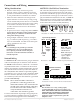
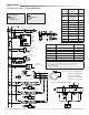
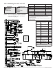
CSE-1102 Air Differential
Pressure Switch
MEP-5372, MEP-7252, MEP-7552, or MEP-7852 Actuators
STE-1416 Duct Averaging
Sensor, Type III
STE-1451 OAT Sensor, Type III
XEE-6311-050 Transformer
See also the
AHU—Additional
Options section
on the last page
for network,
humidification,
and fan speed
options.
AHU 1 OR 2 H / MODULATING C LAYOUT
STE-1402 Duct Sensor, Type III
VEP-45/VEB-43 Fail-Safe Valve with MEP-5372 Actuator
XEE-6311-075 or XEE-6311-100 Transformer
REE-3211 or CVR11C-0/LD96200 Multi-Voltage Relays
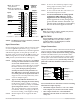
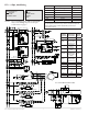
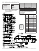
AHU—1 or 2 Heat and Modulating Cool
Output
Terminals
AHU Output
Connections
BACnet
Objects
Analog 9
Optional Outside Air
Damper (OAD/RTD)*
AO9
GND
Ground (for analog
output terminals 7–9)
Analog 8 AO8
Analog 7 Cooling Valve (CLV) AO7
Analog 6
Optional Humidier
Valve (HUM or HUMV)
AO6
GND
Ground (for analog
output terminals 4–6)
Analog 5 AO5
Analog 4 Optional Fan Speed AO4
Relay 3 Optional Heat 2 (W2) BO3
SC 1–3
24 VAC (for relay
terminals 1–3)
Relay 2 Heat 1 (W1) BO2
Relay 1 Fan 1 (G) BO1
*If optional Outside Air Damper is used,
must also have MAT/OAT inputs.
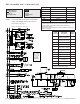
APPLICATION
DEGREESSCALE:°F
APP:
OPT:2H/MODC
ADDITIONALSETUP
AIRHANDLER
ADDITIONALSETUP
DAMPER
FAN
HUMIDITY
OPTIMUMSTART
SENSORS
STAGING
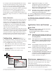
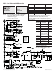
Input Terminals AHU Input Connections BACnet Objects
IN9 Opt. Remote CO
2
Sensor* AI9
IN8 AI8
IN7 Opt. Remote Temp. Sensor* AI7
IN4 Opt. Outside Air Temp. (OAT)** AI4
IN3 Opt. Mixed Air Temp. (MAT)** AI3
GND Ground
IN2 Optional FST or DAT* AI2
*Fan Status (FST), Discharge Air Temperature (DAT), and (not shown
on the diagram) remote temp./CO
2
sensors are optional inputs. Set
pull-up resistor switch positions appropriately (see the Input
Connections section).
**When using the optional Outside Air Damper, MAT/OAT inputs must
also be connected.
NOTE: Do not use REE-3211/CVR11C-0/LD96200
relays with analog outputs! See Output
Connections on page 3.