
Manual

BAC-12xx36/13xx36/14xx36 Series FlexStat 3 Installation Guide, Rev. C
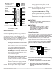
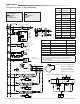
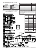
Illustration 5—(BAC-12xx36) Terminals and Connections
Input Connections
Passive input devices require pull-up resistors in the
circuit. For passive input devices (e.g., switch con-
tacts and 10K ohm thermistors) on IN2 through IN4
and IN7 through IN9, set the pull-up switches on
the back of the circuit board to the 10K position. For
active voltage devices, set the switches to the 0–12
VDC position. (See Illustrations 3 through 5.)
NOTE: Unlike the EOL switch pairs, the INPUT
switchpairsmustNOThavebothswitch-
essettothesamedirection—if one of the
pair’s switches is set to the le, for example,
the other must be set to the right (or vice
versa). ALLtheinputpull-upresistor
switchpairsmustbefullylatchedinei-
ther10KOhmor0–12VDCpositioneven
ifaswitchpairhasnoinputconnected! A
single incorrect switch position may cause
errors in multiple inputs.
NOTE: TypeIIorIII10Kohmthermistorscan
beselectedbychangingthemenuseing
in Advanced > Inputs > Input # > Sensor
(see the Conguration section). If a remote
spacetemperaturesensor is connected to
AI7, space temperature can be congured
for onboard, remote, averaging of the two,
the lowest reading, or the highest reading.
NOTE: FlexStat inputs do not support 1K ohm
RTDs.
Output Connections
Connect the device under control between the desired
output terminal and the related SC(SwitchedCom-
monforrelays)orGND(Groundforanalogoutputs)
terminal. (See Illustration 5). For the bank of three
relays, there is one Switched (relay) Common connec-
tion (in place of the GND terminal used with analog
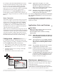
outputs). (See Illustration 6.)
Fortherelaycircuit,the
phasesideoftheACshouldbeconnectedtotheSC
terminal.
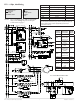
Illustration 6—Switched (Relay) Common and Relays
CAUTION
Do not mistakenly connect 24 VAC to an analog
output ground. This is not the same as a relay’s
switched common. See the backplate’s terminal
label for the correct terminal.
CAUTION
Relays are for Class-2 voltages (24 VAC) only. Do not
connect line voltage to the relays!
Donotaachadevicethatdrawscurrentexceeding
theFlexStat’soutputcapacity:
• Maximumoutputcurrent for individual ANA-
LOGoutputs(4–9)is20mA@12VDC(each).
• Max.outputcurrentis1Aforindividual
RELAYS@24VAC/VDCoratotalof1.5Afor
relays1–3.
IN9
IN8
GND
IN7
+B
–A
IN4
IN3
GND
IN2
Common/–/C
Phase/ /R
Analog 9
GND 7–9
Analog 8
Analog 7
Analog 6
GND 4–6
Analog 5
Analog 4
Relay 3
SC 1–3
Relay 2
Relay 1
Outputs
(Wiring Cutout in Backplate)
MS/TP
Network
Inputs
24 VAC
(Wiring is
dependent on
application)
Inputs
IP/Ethernet
Network
(Optional)
NOTE: IN1 and IN5–6 are
reserved for internal sensors
NOTE: SC = Switched
(relay) Common
NOTE: To use a 4–20 current loop input or map
analog inputs as binary values, see the
FlexStat Application Guide.
NOTE: To use a remote SAE-10xx CO
2
sensor, see
the FlexStat Operation Guide.
NOTE: Formoreinformationonwiringspecic
applications(AHUandFCU),seethe
Applicationssectionstartingonpage5.
(These applications are the packaged pro-
grams selectable from the Advanced > Ap-
plication menu in the BAC-1xxx36 models.)
See also the FlexStat Application Guide.
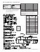
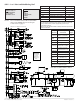
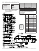
NOTE: OnBAC-13xxxx/14xxxxmodels,terminals
arerotated90°CCW.
Relay 3
SC (Phase) 1–3
Relay 2
Relay 1
One Switched
Common
Connection in
Bank of Three
Normally
Open Relays