
Manual

BAC-12xx36/13xx36/14xx36 Series FlexStat 1 Installation Guide, Rev. C
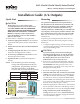
Installation Guide (3/6 Outputs)
BAC-12xx36/13xx36/14xx36 Series FlexStat
™
3 Relays, 6 Analog Outputs, 6 External Inputs
Quick Start 1
Mounting 1
Connections and Wiring 2
Wiring Considerations 2
Network Wiring 2
MS/TP EOL (End-Of-Line) Termination 2
Input Connections 3
Output Connections 3
Power Connection 4
Configuration 4
Applications Notes and Cautions 4
Maintenance 4
Applications 5
FCU (Fan Coil Unit)—2 Pipe, Modulating 5
FCU—4 Pipe, Modulating 6
AHU (Air Handler Unit)—1 Heat and 1 Cool 7
AHU—1 or 2 Heat and Modulating Cool 8
AHU—Modulating Heat and 1 or 2 Cool 9
AHU—Modulating Heat and Modulating Cool 10
AHU—Additional Options 11
Important Notices 11
Additional Resources 11
MountingQuick Start
CAUTION
This document is for 3-relay, 6-analog-output,
6-external-input BAC-12xx36/13xx36/14xx36 series
only. THESE MODELS ARE NOT COMPATIBLE
WITH THE BACKPLATES OF OLDER BAC-10000
SERIES FLEXSTATS (WITH ONLY 3 EXTERNAL
INPUTS)! If replacing an older 3-input FlexStat,
replace the backplate as well. See other installation
guides for other models.
To select and use a FlexStat in an application:
1. Selecttheappropriatemodel for the intended
application and options (see the FlexStat Data
Sheet).
2.
Mountandwiretheunit(seethisInstallation
Guide).
3.
Congure/programtheunit (see the FlexStat
Operation and Application Guides).
4.
Ifnecessary,troubleshootanyissues (see the
FlexStat Operation Guide).
5.
Operatetheunit (see the FlexStat Operation
Guide).
NOTE: This document gives basic mounting,
wiring, and setup information only. For
conguration, programming, operation,
and other information, see the KMC
Controls web site for the latest documents.
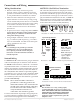
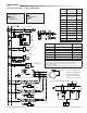
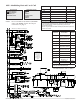
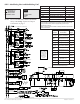
Illustration 1—Dimensions and Installation
C
A
B
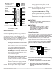
EIA-485 data
port (for quick
network access)
Terminal blocks on
backplate (rotated on
BAC-13xxxx/14xxxx)
Models
Dimensions in Inches (mm)
A B C
BAC-12xxxx (shown) 1.125 (29)
5.551
(141)
4.192 (106)
BAC-13xxxx/14xxxx 1.437 (36.5) 5.192 (132)
Foroptimumtemperaturesensorperformance,
theFlexStatmustbemountedonaninteriorwall
andawayfromheatsources,sunlight,windows,
airvents,andaircirculationobstructions(e.g.,
curtains,furniture).Additionally,foramodelwith
anoccupancysensoroption,installitwhereitwill
haveunobstructedviewofthemosttypicaltrac
area. (See the FlexStat Application Guide for more
information.)
If replacing an existing thermostat, label wires as
needed for reference when removing the existing
thermostat.
1. Complete rough-in wiring at each location prior
to thermostat installation. Cable insulation must
meet local building codes.
CAUTION
To prevent mounting screw heads from touching the
circuit board in the thermostat, use only the mounting
screws supplied by KMC Controls. Using other screws
may damage the FlexStat. Do not turn screws in
farther than necessary to remove the cover.
2. If the cover is locked on the backplate, turn the
hex screws in the boom and top of the FlexStat
CLOCKWISE until they (just) clear the cover.
(See Illustration 1.) Pull the cover away from the
backplate (mounting base).
3. Route the wiring through the backplate.
4. Withtheembossed“UP”andarrowstowardthe
ceiling, fasten the backplate to a wall handy-box.
BAC-12xxxx models mount directly on vertical 2
x 4 inch boxes, but they require an HMO-10000/
HMO-10000W wall mounting plate for horizontal
or 4 x 4 boxes. BAC-13xxxx/14xxxx models mount
directly on any of those types of boxes.
5. Make the appropriate connections to the terminal
blocks. (See the Connections and Wiring section.)
6. Place the FlexStat cover over the backplate while
beingcarefulnottopinchordislodgeany
wiring. Back the hex screws (counterclockwise)
out of the brackets until they engage the FlexStat
cover and hold it in place.
Cover locking hex screws
Embossed “UP” indicator