
Submittal Sheet
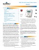
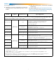
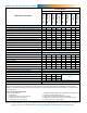
Table Of Contents
- Contents/Cover
- Description and Application
- Features
- Configurability
- Models
- Application/Model Selection Guide
- Specifications, General
- Specifications, Motion Sensor
- Specifications, CO2 Models Only
- Demand Control Ventilation (DCV)
- Accessories
- Dimensions and Connectors
- Sample Installation
- Product and Documentation Awards
- Support

2
◆ Integral energy management control with opti-
mum start, deadband heating and cooling set-
points, and other advanced features to assure
comfort while maximizing energy savings
◆ Schedules can easily be set uniquely by the entire
week (Mon.–Sun.), weekdays (Mon.–Fri.), week-
end (Sat.–Sun.), individual days, and/or holidays;
six On/O and independent heating and cooling
setpoint periods are available per day
◆ Three levels of password-protected access (user/
operator/administrator) prevent disruption of
operation and conguration—plus Hospitality
mode and Locked User Interface mode oer ad-
ditional tamper resistance
◆ Integral temperature and optional humidity, mo-
tion, and/or CO
2
sensors
◆ All models have 72-hour power (capacitor)
backup and a real time clock for network time
synchronization or full stand alone operation
◆ Models functionally replace most Viconics and
other competitors’ products
Inputs
◆ Six analog inputs for additional congurable
remote external sensors, such as remote space
temperature (with averaging, highest, and low-
est options), remote CO
2
, OAT, MAT, DAT, water
supply temperature, fan status, and other sensors
◆ Inputs accept industry-standard 10K ohm (Type
II or III) thermistor sensors, dry contacts, or 0–12
VDC active sensors
◆ Input overvoltage protection (24 VAC, continuous)
◆ 12-bit analog-to-digital conversion on inputs
Outputs
◆ Nine outputs, analog and binary (relays)
◆ Each short-circuit protected analog output
capable of driving up to 20 mA (at 0–12 VDC)
◆ The NO, SPST (Form “A”) relays carry 1 A max.
per relay or 1.5 A per bank of 3 relays (relays 1–3
and 4–6) @ 24 VAC/VDC
◆ 8-bit PWM digital-to-analog conversion on out-
puts
Installation
◆ Backplate mounts on a standard vertical 2 x
4-inch wall handy-box (or, with an HMO-10000
adapter, a horizontal or 4 x 4 handy-box), and the
cover is secured to the backplate by two con-
cealed hex screws
Configurability
I/O
◆ Up to 10 analog input objects (IN1 is space tem-
perature, IN2–IN4 and IN7–IN9 are 0–12 VDC in-
puts, IN5 is reserved for humidity, IN6 is reserved
for motion detection, IN10 is reserved for CO
2
)
◆ Up to 9 analog or binary output objects
Value
◆ 150 analog value objects
◆ 100 binary value objects
◆ 40 multi-state value objects (with up to 16 states
each)
Program and control
◆ 20 PID loop objects
◆ 10 program objects (contains a library of 5 built-
in programs and customized Control Basic
programming in the other 5 program objects can
be done through BACstage or TotalControl)
Schedules and trends
◆ 2 schedule objects
◆ 1 calendar object
◆ 8 trend objects, each of which holds 256 samples
Alarms and events
◆ 5 notication class (alarm/event) objects
◆ 10 event enrollment objects
◆ Two-piece design provides easy wiring and instal-
lation (see Dimensions and Connectors on page 9)
Connections
◆ Screw terminal blocks, wire size 14–22 AWG, for
inputs, outputs, power, and MS/TP network
◆ “E” versions add an RJ-45 jack
◆ A four-pin EIA-485 (formerly RS-485) data port
on the underside of the case enables easy tempo-
rary computer connection to the BACnet network
(access with a KMD-5624 cable—requires use of
KMD-5576 or third-party interface)
BACnet Communication and Standards
◆ Integral peer-to-peer BACnet MS/TP LAN net-
work communications on all models (
with con-
gurable baud rate from 9600 to 76.8K baud)
◆ “E” versions add BACnet over Ethernet, BACnet
over IP, and BACnet over IP as Foreign Device
◆ Meets or exceeds BACnet AAC specications in
the ANSI/ASHRAE BACnet Standard 135-2008