
Install Instructions
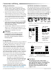
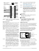
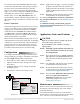
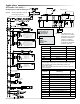
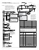
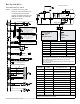
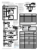
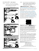
Table Of Contents

BAC-12xx63/13xx63/14xx63 Series FlexStat 8 Installation Guide, Rev. E
4-PIPE MODULATING OPTION
(See the FCU—Other Options section on the next page for more options)
XEE-6311-050 Transformer
REE-3211 or CVR11C-0/LD96200 Multi-Voltage Relays
FCU 4-PIPE
MODULATING LAYOUT
CSE-1102 Air Differential
Pressure Switch
VEB-43 Valves with
MEP-4002V Actuators
SET SWITCHES FOR...
OPERATION: CW
INPUT RANGE: 0–10 VDC
SET SWITCHES FOR...
OPERATION: CCW
INPUT RANGE: 0–10 VDC
Fan Coil Unit (FCU)—
2 or 4 Pipe, Modulating or 2 Position
Output Terminals
(BAC-12xxx63C)
FCU Output Connections
BACnet
Objects
2-Pipe 4-Pipe
Analog 9 AO9
GND
Ground
(for analog output terminals 7–9)
Analog 8
Heat Valve,
Proportional (HTV)
AO8
Analog 7
Valve,
Proportional (VLV)
Cool Valve,
Proportional (CLV)
AO7
Relay 6 BO6
SC 4–6 24 VAC (for relay terminals 4–6)
Relay 5
Heat Valve,
2-Position (HTV)
BO5
Relay 4
Valve,
2-Position (VLV)
Cool Valve,
2-Position (CLV)
BO4
Relay 3 Fan 3 BO3
SC 1–3 24 VAC (for relay terminals 1–3)
Relay 2 Fan 2 BO2
Relay 1 Fan 1 BO1
APPLICATION
DEGREES SCALE: °F
APP:
OPT: 4–PIPE
ADDITIONAL SETUP
FAN COIL
ADDITIONAL SETUP
FAN
HUMIDITY
OPTIMUM START
SENSORS
VALVE
NOTE: To see Humidity
options in the
Additional Setup
menu, select the
4-Pipe option.
NOTE: Do not
use REE-3211/
CVR11C-0/
LD96200 relays
with analog out-
puts! See Output
Connections on
page 3.
Input Terminals FCU Input Connections BACnet Objects
IN9 Opt. Remote CO
2
Sensor* AI9
IN8 AI8
IN7 Opt. Remote Temp. Sensor* AI7
IN4 AI4
IN3 Supply Water Temp. (W-TMP)** AI3
GND Ground
IN2 Optional FST* AI2
*Fan Status (FST) and (not shown on the diagram) remote temp./
CO
2
sensors are optional inputs. Set pull-up resistor switch positions
appropriately (see the Input Connections section).
**W-TMP is for 2-pipe applications only (see drawings on the next page)
NOTE: In rmware earlier
than R2.1.0.18,
an option for a
DAT on IN2 was
available for a
built-in trend log.
For later rmware,
use KMC Connect
or TotalControl
to create a custom
trend if this is
desired.