
Install Instructions
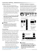
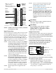
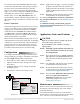
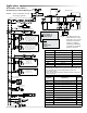
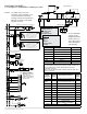
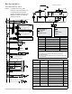
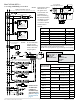
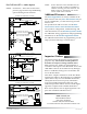
Table Of Contents

BAC-12xx63/13xx63/14xx63 Series FlexStat 2 Installation Guide, Rev. E
Connections and Wiring
Illustration 2—MS/TP Network End-Of-Line Termination
Illustration 3—BAC-12xxxx EOL/Pull-Up Switch Positions
Wiring Considerations
• Because of the many connections (power,
network, inputs, outputs, and their respective
grounds or switched commons), be sure wiring
is well planned before installation of conduit!
• Make sure that conduit for all wiring has ad-
equate diameter for all necessary wiring. Using
1-inch conduit and junction boxes is recommend-
ed! Use external junction boxes above the ceiling
or in another convenient location as needed
to make connections that run to the FlexStat’s
junction box.
• To prevent excessive voltage drop, use a conduc-
tor size that is adequate for the wiring length!
Allow plenty of “cushion” to allow for tran-
sient peaks during startup.
• Using multiple conductor wires for all relevant
inputs (e.g., 8 conductor) and outputs (e.g., 12
conductor) is recommended. Grounds for all the
inputs can be combined on one wire.
CAUTION
To avoid damage from ground loops and other
communication issues in networked FlexStats,
correct phasing on MS/TP network and power
connections on ALL the networked controllers is
critically important.
Network Wiring
For Ethernet or IP communications, plug an Ethernet
cable into the RJ-45 jack on the back of the FlexStat.
For MS/TP communications, connect the –A termi-
nals in parallel with all other –A terminals on the
network and the +B terminals in parallel with all
other +B terminals. (See Illustrations 2 and 4.) Con-
nect the shields of the cable (Belden cable #82760 or
equivalent) together at each device. Use a wire nut or
the S terminal in KMC BACnet controllers. (FlexStats,
however, do not have an S terminal.) Connect the
cable shield to a good earth ground at one end only.
NOTE: The S terminal in KMC controllers is
provided as a connecting point for the
shield. The terminal is not connected to the
ground of the controller. When connecting
to controllers from other manufacturers,
verify the shield connection is not
connected to the controller’s ground.
For more information on principles and good practic-
es when connecting an MS/TP network, see Planning
BACnet Networks (Application Note AN0404A).
MS/TP EOL (End-Of-Line) Termination
The controllers/thermostats on the physical ends of
an EIA-485 wiring segment must have end-of-line
termination installed for proper network operation.
(See Illustrations 2 through 4.) If a FlexStat is at the
physical end of the MS/TP network line, set both the
EOL termination switches to On (to the right/up)
on the back of the circuit board. If not on the end,
ensure that both switches are O (left/down).
10K Ohm
0-12 VDC
Input Pull-Up Switches
EOL
Switches
ON
OFF
Switch Pushed Up
Pushed Down
IN2 IN3 IN4 IN7 IN8
IN9
Illustration 4—BAC-13xxxx/14xxxx Switch Positions
10K Ω
0-12 V
Input Pull-Up Switches
ON
OFF
Switch
Pushed
Right
IN2
IN3
IN4
IN7
IN8
IN9
NOTE: 10K Ω inputs
are configurable for
Type II or Type III
thermistors in
FlexStat’s menu.
NOTE: EOL = End
Of Line of BACnet
MS/TP network.
EOL Switches
Switch
Pushed
Left
CAUTION
This document is for 6-relay, 3-analog-output,
6-external-input BAC-12xx63/13xx63/14xx63 series
ONLY. THESE MODELS ARE NOT COMPATIBLE WITH
THE BACKPLATES OF OLDER BAC-10000 SERIES
FLEXSTATS (WITH ONLY 3 EXTERNAL INPUTS)!
If replacing an older 3-input FlexStat, replace the
backplate as well.