Application Guide KMC Controls, 19476 Industrial Drive, New Paris, IN 46553 / 877-444-5622 / Fax: 574-831-5252 / www.kmccontrols.
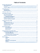
Table of Contents Managing a KMC Conquest AFMS About the AFMS Module Prerequisites Setting Up an AFMS 3 3 3 3 Setting AFMS Parameters Before Beginning Setting the Parameters 4 4 4 Calibrating the AFMS's Sensors 6 Running AFMS Learning Mode Before Starting Learning Mode Checking Learn Ready Status Interpreting Learn Ready Status Manually Starting Learning Mode Enabling Learning Mode to Auto Start Alternative to Running Learning Mode 7 7 7 7 8 8 9 Controlling Airflow with an AFMS About Controlling Out
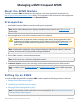
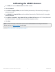
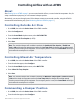
Managing a KMC Conquest AFMS About the AFMS Module The KMC Commander AFMS module allows you to configure, control, tune, and monitor the operation of a KMC Conquest Airflow Measurement System (AFMS). The icon appears in KMC Commander's side navigation bar after an AFMS controller is discovered and saved in Networks Explorer. Prerequisites 1. Install a KMC Conquest AFMS (the controller and all system components).
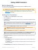
Setting AFMS Parameters Before Beginning Before setting a KMC Conquest Airflow Measurement System's parameters in AFMS, ensure that the Prerequisites on page 3 have been met. Caution: Select the appropriate application on the AFMS controller before configuring other settings. Changing applications after configuration will restore most parameters to their defaults. See "Selecting an Application" in the KMC Conquest AFMS NetSensor Application Guide, found on any AFMS controller's product page.
9. Select ON for Learn Damper Span. Note: Before the AFMS controller can run Learning Mode, it must learn the minimum and maximum incline of the damper using the inclinometer. 10. Select Save. Note: "The process of updating points is successfully started" appears briefly. When the damper has stroked the opening, Damper Span Learned will report LEARNED. Continue to Calibrating the AFMS's Sensors on page 6.
Calibrating the AFMS's Sensors 1. Go to AFMS, then select the Device Name of the AFMS controller. 2. Select the Tune tab. 3. Under Offset for Supply Air Flow, enter the CFM offset (determined by a TAB technician) for the supply air pressure transducer. 4. Under Multiplier for Supply Air Flow, enter the multiplier (determined by a TAB technician) for the supply air pressure transducer. 5.
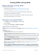
Running AFMS Learning Mode Before Starting Learning Mode For valid results, first ensure that: l The parameters are set correctly. (See Setting AFMS Parameters on page 4.) l The sensors are calibrated. (See Calibrating the AFMS's Sensors on page 6.) l The supply air fan is running at a normal, steady rate (without hunting or sporadic spikes). l If the unit has a heat recovery wheel, it is turned off. l If any heating or cooling sources are located upstream of the MAT sensor, they are turned off.
l Check Min Delta Temp. If the current ΔT (the absolute difference between the outside and return air temperatures) is less than the minimum difference allowed, then continue to Enabling Learning Mode to Auto Start on page 8. Note: Go to Monitor to find Outside Air Temp and Return Air Temp. Calculate the absolute difference, then compare to Min Delta Temp. Manually Starting Learning Mode If Learn Ready reports READY (see Checking Learn Ready Status on page 7), you may start Learning Mode manually. 1.
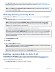
Note: If the ΔT becomes less than the Min Delta Temp, the AFMS controller will abort Learning Mode. This is to insure that the controller does not receive unusable learning samples. 10°F or more Min Delta Temp is recommended. 2. Leave Auto Start Delta Temp set to the default, or adjust it if needed. Note: When the ΔT reaches the Auto Start Delta Temp, Learning Mode will start. Learning Mode will complete if the ΔT remains greater than the Min Delta Temp for the entire duration.
Controlling Airflow with an AFMS About After Setting Up an AFMS on page 3, you can control outside air flow, or control mixed air temperature. Also, for setup or maintenance purposes, you can command a damper position. Alternatively, you can pass through control of the damper actuator to an external controller, using the AFMS for measurement and monitoring only. (See Monitoring with an AFMS on page 12.) Controlling Outside Air Flow 1. Go to AFMS, then select the Device Name of the AFMS controller. 2.
3. From the Control Mode drop-down menu, select DMPR POSITION CTRL. 4. Enter an Outside Air Damper Setpoint (0–100% open). 5. Select Save. Note: The AFMS controller will command the damper to the Outside Air Damper Setpoint. If Enable Low Limit is ON and the mixed air temperature reaches the Low Temp Limit, the damper will modulate toward closed to prevent freezing of the equipment. If an occupancy sensor is used, this Control Mode will only be active when the served space is occupied.
Monitoring with an AFMS Accessing Monitoring 1. Go to AFMS, then select the Device Name of the AFMS controller. 2. Select the Monitor tab. Monitoring Operation Label Outside Air Flow Description The AFMS controller's current outside air CFM calculation displays here. NORMAL = No faults are detected. AFMS Status LEARN MODE = Learning Mode is ON. (See Running AFMS Learning Mode on page 7.) SPAN MODE = Learn Damper Span is ON. (See Setting AFMS Parameters on page 4.
Label Description Outside Air Control Fault If the saved Control Mode is OA FLOW CTRL (see Controlling Outside Air Flow on page 10), FAULT will display if Outside Air Flow is more than 15% off from the Outside Air Flow Setpoint for longer than the Stroke Time (Seconds) (found under Configure > Damper). This indicates that the damper is not moving properly.
Accessing the Damper Characterization Table Manually Entering Damper Characterization Data While not ideal, the damper characterization data can be calculated and entered manually in the AFMS Table. This should only be done if — in the allotted time for Setting Up an AFMS on page 3 — the ΔT is unlikely to be greater than the Min Delta Temp for the duration of Learning Mode. In that case, for reliability, running Learning Mode at a later available time is still recommended. Accessing the AFMS Table 1.
Note: See Controlling Airflow with an AFMS on page 10 for how to set the outside air damper to the required positions for the measurements. Note: See Monitoring with an AFMS on page 12 for where to find the sensor readings. Continue to Managing a KMC Conquest AFMS on page 3. Verifying the Damper Characterization Data Should the damper characterization data require verification, measurements should only be made using NISTtraceable instruments and the method described in ASHRAE Standard 111.
Important Notices Trademarks KMC Commander®, KMC Conquest™, KMC Controls®, and the KMC logo are registered trademarks of KMC Controls, Inc. All other products or name brands mentioned are trademarks of their respective companies or organizations. All rights reserved. Patents Pat. https://www.kmccontrols.com/patents/ Terms of Use https://www.kmccontrols.com/terms/ EULA (End User License Agreement) https://www.kmccontrols.