
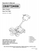
Manual

NOTE:Thisunitis shippedwithoutgasolineor oil inthe engine.Be
certainto serviceenginewithgasolineandoil as instructedin the
Operationsectionof this manualbeforeoperatingyourmachine.
NOTE:Referenceto rightand lefthandsideof the Tilleris observed
fromthe operatingposition.
OPENING CARTON
1. Removeall staplesfromaroundthe bottomof the perimeter.
2. Removethe cartonfromthe skid.
3. Removeall looseparts.
4. Removeloosepackingmaterial.
REMOVING UNIT FROM SKID
1. Thetiller is heavy,do notattemptto removeit fromthe skiduntil
instructedtodo so intheseassemblysteps.
2. Checkcartonthoroughlyfor anyotherlooseparts.
LOOSE PARTS IN CARTON
• HandlebarAssembly
• Tiller
• EngineOil
• Operator'sManual
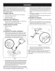
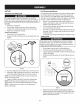
ATTACHING THE HANDLE ASSEMBLY
1. Installthe handleontothetiller usingthe hardwarepre-installed
onthe handlemountingbrackets.Thisconsistsof a 5/16-18x
3.00"hex bolt,a handlecrankassembly,retainerbracketandtwo
5/16-18flangelocknuts. Removethishardwarefromthe handle
mountingbracketson the tiller.Referto Figure1inset.
f -_,
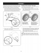
3. Installthe handle-crankadjustmentrod intothe topholeof the
mountingbracketfromthe left handsideof the handleassembly,
securewiththe otherflangelocknut previouslyremoved.Fit
the hexend of the retainerbracketoverthe flangelocknut.See
Figure1.
4. Tightenthe hexbolt installedin Step2 atthis time.Becarefulnot
to overtightenthishardware.
5. Withthe handlein the desiredposition,tightenthe handlecrank
adjustmentrodat thistime.
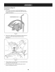
ATTACHING THE CABLES
1. Routethe twocablesalongthe handleassemblyon the righthand
side.
2. Connectthe reversecable(Red)to the reversecablecontrolby
feedingthez-hookthroughthe holeon thereversecablecontrol
fromthe insidetowardstheoutside.SeeFigure2.
f ---
/
Figure2
3. Connecttheforwarddrivecable(Black)to the clutchbailby
feedingthez-hookthroughthe holeon theclutchbailfromthe
outsidetowardsthe inside.SeeFigure2.
NOTE:Testthefunctionof the reverseclutchby pullingthe reverse
handleand releasingit.The handleshouldreturntoits neutral
position.If it doesn't,contactCustomerSupportforassistanceorthe
nearestdealer.
Figure1
2. Insertthe handleintothe handlemountingbrackets,liningupthe
pre-drilledholes.Insertthe5/16-18x 3.00"hexbolt inthebottom
holefromthe left handside throughto the otherside.Placethe
roundholeendof the hex retainerbracketoverthe hexbolt and
securelooselywitha bellwasherand5/16-18flangelocknut
removedearlier.Referto Figure1inset.
NOTE:Thebellwashershouldbepositionedwiththetopd thebellshape
towardsthehexnutwhichwillcreatetensionandfurthersecuretheflange
locknutoncetightened.Donottightenthishardwareatthistime. 7