
User's Manual

10
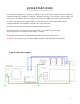
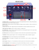
REAR PANEL
12
1
2
3
4
5
6
7
8
9
10
1. Band Data Port: Connect Band Data of the transceiver through Band Data Interface Cable (Sold separately).
See Band Data connection details starting on page 13.
2. Remote Port: This port provides low power high/low voltages from the controller to connect accessories, for
details see page 13.
3. Main Switch: Main power supply interrupter. Recommended for total power shutdown when not in use.
5. IEC 320 C14 AC Outlet: Connect to either a 120VAC or a 240VAC line.
4. Ground Screw: Connect directly to physical ground. Do not make ground loops. Do not connect Ferrite
Clamps or RF Chokes to this ground screw.
6. Air Flow Area: Do not block this area and space it at least 6 inches from any obstruction for proper airflow.
7. USB Port: Remotely operate amp from a PC via a USB Type B (Printer) cable, for details see page 12.
8. SO239 RF Input: Do not exceed an input level of more than 60 Watts.
9. RCA PTT Plug: This triggers the Amplifier from your transceiver. Never connect a Soft-Key Keying
Interface Box.
10. ALC Input: Voltage (-2 to -7V) automatically controls the power level of the transceiver (Optional).
11. ALC Adjustment: An ALC adjustment can be performed with a Philips screwdriver, see page 11.
12. SO239 RF Outputs (3): WARNING: NEVER disconnect any antenna during transmission, as there may be
a possibility of radio frequency burns or fire.
11