
Product Manual

Page 12 of 25
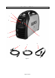
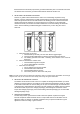
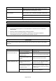
Reference
Subassembly
1
Input Power Indicator Light
2
Weld Process Selector Switch
3
Output Amperage Control
4
Ground Cable and Clamp
5
Negative (-) Weld Output Terminal
6
Electrode Holder and Cable
7
Positive (+) Weld Output Terminal
8
Shoulder Strap
9
Alarm/Overload Indicator Light
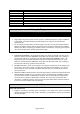
Setting Up Equipment
⚠WARNING
ELECTRIC SHOCK CAN KILL!
High voltage danger from power source! Consult a qualified electrician for proper installation
of receptacle. This welder must be grounded while in use to protect the operator from
electrical shock.
Do not remove grounding prong or alter the plug in any way. Use only the supplied adapter
between the welder's power cord and the power source receptacle. Make sure the POWER
switch is OFF when connecting your welder's power cord directly to a properly grounded 120
VAC, 60 HZ, Single Phase, 20 Amp input power supply.
1. POWER REQUIREMENT - AC single phase 120V (110-120V), 60 HZ with a 20 amp circuit
breaker is required. DO NOT OPERATE THIS UNIT if the ACTUAL power source voltage is
less than 105 volts AC or greater than 132 volts AC.POWER REQUIREMENT 120V - AC
single phase 120V (110-130V) 50/60 HZ fused with a 20 amp time delayed fuse or circuit
breaker is required. DO NOT OPERATE THIS UNIT if the ACTUAL power source voltage is
less than 110 volts AC or greater than 130 volts AC.
2. EXTENSION CORD - We do not recommend an extension cord because of the voltage drop
they produce. This drop in voltage can affect the performance of the welder. If you need to
use an extension cord, check with a qualified electrician and your local electrical codes for
your specific area.
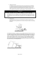
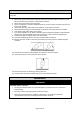
3. WELDING CABLE INSTALLATION – Most DC Stick welding is performed using DC Electrode
Positive (DCEP) welding current. This means that the electrode holder and welding cable is
connected to the Positive (+) Weld Output Terminal. The Ground Cable and Clamp is then
connected to the Negative (-) Weld Output Terminal. The connectors are twist-lock style
connectors. Completely insert the connector into the proper weld output receptacle and then
turn the connector clockwise until snug and tight.
⚠CAUTION
Make Tight Connections
Improper connections, including loose connections in the weld circuit, lead to resistance
causing excessive heat and may result in damage to your equipment. Insure all connections
are snug and tight.