
Operation Manual
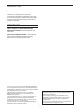

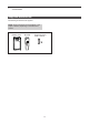
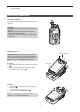

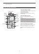
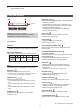
Table Of Contents
- IMPORTANT
- Section 1 ACCESSORIES
- Section 2 PREPARATION
- Section 3 BASIC OPERATION
- Section 4 ADVANCED OPERATION
- Section 5 SCAN OPERATION
- Section 6 MENU SCREEN
- Section 7 NXDN™ OPERATION
- NXDN™ system operation
- Transmitting a call
- Receiving a call
- Roaming function (For Multi-site Trunking operation)
- Site Lock function (For Multi-site Trunking operation)
- Site Select function (For Multi-site Trunking operation)
- Incoming list
- Outgoing list
- Encryption function
- Over The Air Programming (OTAP) function
- Section 8 MDC 1200 SYSTEM OPERATION
- Section 9 BIIS 1200 SYSTEM OPERATION
- Section 10 VOICE RECORDER FUNCTIONS
- Section 11 Bluetooth® OPERATION
- Bluetooth® Wireless Technology operation
- Turning ON the Bluetooth® function
- Pairing with a headset or a data device
- Headset settings
- Accepting a pairing request from a Bluetooth® device
- Disconnecting from a Bluetooth® device
- Deleting a Bluetooth® device from the pairing list
- Resetting the installed Bluetooth® unit
- The maximum number of paired devices
- Section 12 OTHERS
- Section 13 OPTIONS
2
PANEL DESCRIPTION
2-3
Individual-3
► Continued on the next page
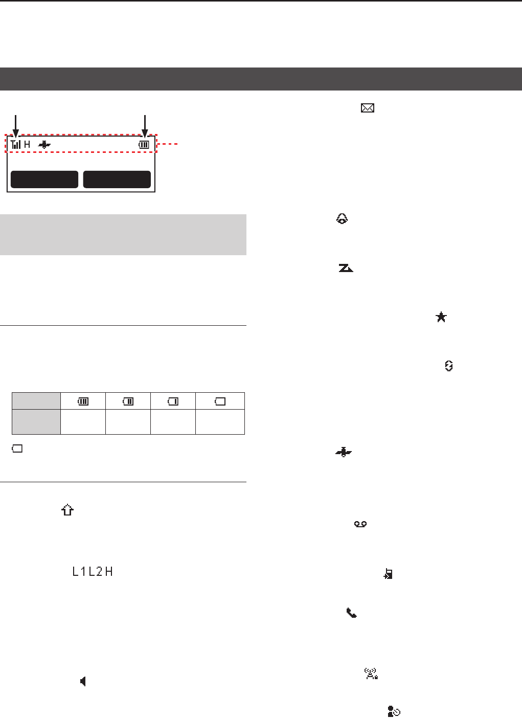
Function display
NOTE: The screen is an example�
The displayed position of each icon may differ,
depending on the function being used�
Call Scan
D Icon Area
Indicators
q SIGNAL STRENGTH INDICATOR
Displays the relative receive signal strength level�
w BATTERY INDICATOR
Displayed or blinks to indicate the battery status�
Indication
Battery
status
Full Mid
Charging
required
Battery
exhausted
blinks when the battery is exhausted�
Icons
The following icons are displayed in the Icon Area�
SHIFT ICON
Displayed when the Shift function is ON�
L A user can use a Software key’s secondary function in
the Shift mode� Ask your dealer for details�
POWER ICON
Displays the output power level�
• “ L1” is displayed when the output power is set to
Low�
• “ L2” is displayed when the output power is set to
Mid�
• “ H” is displayed when the output power is set to
High�
AUDIBLE ICON
Displayed when the channel is in the ‘audible’
(unmuted) mode�
MESSAGE ICON
• Blinks after messages (Message or Status Message)
have been received�
• Stops blinking when the screen is changed, or any
key is pushed, but is displayed if unread messages
are still in the Message memory�
• Disappears when all messages in the Message
memory have been read�
BELL ICON
Displayed when a matching signal is received,
depending on the presetting�
SCAN ICON
• Displayed when a scan is paused�
• Blinks while scanning�
SCAN TARGET CHANNEL ICON
Displayed when the channel is selected as a scan
target channel�
SCRAMBLER/ENCRYPTION ICON
In the Analog mode:
• Displayed when the Voice Scrambler function is ON�
In the Digital mode:
• Displayed when the Encryption function is ON�
• Blinks while decoding an encrypted signal�
GPS ICON*
• Displayed when valid position data is received�
• Blinks while searching for satellites or calculating
position data�
* HM-233GP is required to use the GPS function�
RECORD ICON
• Displayed when the Record function is ON�
• Blinks while recording audio�
TALK AROUND ICON
Displayed when the Talk Around function is ON�
PHONE ICON
• Displayed when the transceiver is connected to a
telephone network on the selected channel�
• Blinks while receiving a phone call�
SITE LOCK ICON
Displayed when the Site Lock function is ON�
LONE WORKER ICON
Displayed when the Lone Worker function is ON�
Icon Area
q w