
Operation Manual


Dante Bridge Operation Manual rev 2.1.0
9
12. Operation
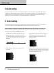
5. Offer the Accessory with its mounting brackets up
to the reverse side of the Mounting Panel, and x it in
place using the two sets of screws, washers and nuts
removed in 1.
Dante
BRIDGE
POWER NET DANTE
EXT POE DATA SYNC D ATA
Note that the holes at the rear ends of the brackets
may be used as cable tie-o points if desired.
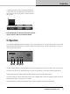
12. Operation
Once the Dante Bridge has been connected to the computer/switch and to the audio devices (and to the power
supply if applicable), then there are no further adjustments required on the unit itself. The indicators on the front
of the unit operate as follows:
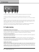
Dante
BRIDGE
POWER NET DANTE
EXT POE DATA SYNC DATA
1 2 3 4 5
The EXT Power indicator (1) illuminates when DC power is applied to the EXT Power socket on the rear of the unit.
The PoE Power indicator (2) illuminates when DC power is provided by a Power Over Ethernet (PoE) Switch.
The Net DATA indicator (3) illuminates when data is being received from the VNET network.
The Dante SYNC (4) indicator illuminates when the unit is supplied with a Dante Clock signal. Note that it will not
illuminate if the Device is acting as a clock master.
The Dante DATA (5) indicator will illuminate when the unit is receiving control data over Ethernet.