DN9650/DN9652 Network Bridge Operator Manual Midas Klark Teknik Limited, Klark Industrial Park, Walter Nash Road, Kidderminster. Worcestershire. DY11 7HJ. England. Tel: +44 1562 741515 Fax: +44 1562 745371 Email: info@midasklarkteknik.com Website: www.klarkteknik.com DN9650/DN9652 Network Bridge — Operator Manual DOC02-DN9650/52 Issue A — February 2011 © Red Chip Company Ltd. In line with the company’s policy of continual improvement, specifications and function may be subject to change without notice.
IMPORTANT SAFETY INSTRUCTIONS The lightning flash with arrowhead symbol within an equilateral triangle is intended to alert the user to the presence of uninsulated “dangerous voltage” within the product's enclosure that may be of sufficient magnitude to constitute a risk of electric shock to persons. The exclamation point within an equilateral triangle is intended to alert the user to the presence of important operating and maintenance (servicing) instructions in the literature accompanying the product.
INSTRUCTIONS DE SÉCURITÉ IMPORTANTES Le symbole représentant un éclair fléché dans un triangle équilatéral a pour but d'alerter l'utilisateur de la présence d'une "tension dangereuse" non isolée à l'intérieur du boîtier, pouvant être d'une force suffisante pour constituer un risque d'électrocution.
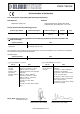
EC-Declaration of Conformity Klark Teknik EC-Declaration of Conformity The undersigned, representing the following manufacturer Manufacturer: Address: Midas Klark Teknik Ltd. Klark Industrial Park, Walter Nash Road, Kidderminster. Worcestershire. DY11 7HJ. hereby declares that the following product Product Type Number Product Description Nominal Voltage(s) Current Freq.
EC-Declaration of Conformity Klark Teknik EC-Declaration of Conformity The undersigned, representing the following manufacturer Manufacturer: Address: Midas Klark Teknik Ltd. Klark Industrial Park, Walter Nash Road, Kidderminster. Worcestershire. DY11 7HJ. hereby declares that the following product Product Type Number Product Description Nominal Voltage(s) Current Freq.
Licences The following are the license agreements applicable to this equipment. End-User Licence Agreement for Midas™ and Klark Teknik™ Software IMPORTANT - Please read this document carefully before using this Midas™ or Klark Teknik™ Product. This is an agreement governing your use of software or other machine instructions already installed on this Midas™ or Klark Teknik™ Product, as well as other software that we provide for installation on this Product.
DATE INFORMATION. You understand that the Company may update or revise the Software but in so doing incurs no obligation to furnish such updates to you. However, the Company may in its discretion make updates available from time to time upon such terms and conditions as it shall determine.
and the Courts of England and Wales will have exclusive jurisdiction to hear and decide any dispute concerning it or its formation. No breach by you of any provision of this Licence shall be waived or discharged except with the express written consent of the Company and no failure or delay by the Company to exercise any of its rights under this Licence shall operate as a waiver thereof and no single or partial exercise of any such right shall prevent any other or further exercise of that or any other right.
Contents Chapter 1 Getting Started. . . . . . . . . . . . . . . . . . . . . . . . . . . . . . . 1 Unpacking . . . . . . . . . . . . . . . . . . . . . . . . . . . . . . . . . . . . . . . Installation . . . . . . . . . . . . . . . . . . . . . . . . . . . . . . . . . . . . . . Handling the equipment . . . . . . . . . . . . . . . . . . . . . . . . . . . Radio frequency interference - Class A device . . . . . . . . . . . . Electric fields . . . . . . . . . . . . . . . . . . . . . . . . . . . . . . . . . . .
Contents Appendix C Service Information . . . . . . . . . . . . . . . . . . . . . . . . . 33 Restoring the factory defaults . . . . Routine maintenance . . . . . . . . . . Cleaning . . . . . . . . . . . . . . . . . . . Checking/replacing the mains fuse Special accessories . . . . . . . . . . . Optional equipment . . . . . . . . . . . Equipment disposal . . . . . . . . . . . xiv . . . . . . . . . . . . . . . . . . . . . . . . . . . . . . . . . . . . . . . . . . . . . . . . . . . . . . . . . . . .
Chapter 1: Getting Started This chapter shows you how to prepare the DN965X for operation, which includes: • Unpacking • Installation • Connecting up • Switching the unit on/off • Initial configuration Before installing, setting up or operating this equipment, make sure you have read and fully understand all of the “IMPORTANT SAFETY INSTRUCTIONS” at the front of this document. Important: You must set up the IP address and netmask of your computer (PC/Mac) before using it for the first time.
Chapter 1: Getting Started Handling the equipment Completely isolate the equipment electrically and disconnect all cables from the equipment before moving it. When lifting or moving the equipment, always take its size and weight into consideration. Radio frequency interference - Class A device This equipment has been tested and found to comply with the limits for a Class A digital device, pursuant to Part 15 of the FCC Rules.
Powering the unit Word clock target Word clock source Video black burst source DN9652 rear panel Third party network module Third party network module Network module A Network module B Typical DN9652 audio connection configuration Powering the unit This section shows you how to connect the unit to the mains, switch the unit on/off and electrically isolate the unit.
Chapter 1: Getting Started Configuring the unit for the first time Important: Before you use the unit for the first time, you must configure your computer with the IP address and netmask to suit the range used by the DN965X. Before you can use the DN965X as a network bridge, you must first configure it by choosing the type of network module card(s) that are fitted in the unit and then setting them up. Configuration involves connecting the DN965X to a computer running an up-to-date web browser.
Configuring the unit for the first time 6 The DN965X NETWORK BRIDGE CONFIGURATION menu will open in the web browser’s Klark Teknik DN965X Configuration tab. >> To select which network card(s) are fitted in the unit 1 In the configuration menu, click Change Module Type in the desired network module section. If no network module type has been set up, its section will look similar to the one shown right. On the DN9650, network module B is always a Klark Teknik 3-Port AES50 Module.
Chapter 1: Getting Started 6 DN9650/DN9652 Network Bridge Operator Manual
Chapter 2: Overview Thank you for purchasing a Klark Teknik DN9650/DN9652 Network Bridge. The DN965X is a user-friendly, high-performance, digital audio network bridge. Both the DN9650 and DN9652 units compliment each other.
Chapter 2: Overview Front and rear panels of the DN9652 Network Bridge Since the network clock domains (A and B) contain digital audio, an intermediate asynchronous sample rate converter (ASRC) effectively resamples the audio as it passes between them, while obeying Nyquist sampling theory1.
Host software version and updates • Supports up to 64 bi-directional channels of 24-bit, 96kHz audio per network or AES50 port (DN9650 only) with 1:1 channel mapping. • Supports operation at 48kHz and 96kHz sampling frequencies. Bi-directional ASRC on every channel with bypass facility to isolate network domains. • High channel count asynchronous sample rate conversion (ASRC). • Platform-independent web browser configuration interface software hosted on integrated Linux web server.
Chapter 2: Overview About this manual This is the operator manual for the DN9650 and DN9652 Network Bridge units. It is intended to help get your units installed and in operation as quickly as possible by giving you unpacking, installation, connection, configuration and setting up instructions. To help familiarise you with the units, there is a description of the front and rear panels, along with easy-to-follow user instructions. When referring to both DN9650 and DN9652 type units you will see “DN965X”.
Chapter 3: Front Panel This chapter describes the front panel of the DN9650 and DN9652 units, which comprise the following. 3 1 2 4 5 6 5 Front panel of the DN9650 (top) and DN9652 (bottom) Item Description Illustration 1 Ventilation grill Air intake for internal cooling via an internal fan. Do not obstruct. N/A 2 CONTROL section A green ETHERNET LED illuminates to show the communication status between unit and PC, as follows: 3 4 • Illuminated = traffic detected.
Chapter 3: Front Panel Item Description 5 NETWORK section This section shows the status of the network module connection, as follows: 6 Illustration • Constantly illuminated green with red extinguished = cable/fibre is synchronised, but there is no audio activity. • Pulsating green with red extinguished = cable/fibre is on with audio activity. • Green extinguished with red illuminated = cable/fibre are off.
Front panel Table 1: DN9650 ASRC LED status AES50 OUTPUT LEDs ASRC ENABLED LED NETWORK OUTPUT LEDs Status Yellow LED = off Red LED = off Off Yellow LED = off Red LED = off When ASRC is disabled, AES50 and network output indication does not play any role. Yellow LED = on Red LED = off On Any condition The network clock output is working. The AES50 output clock is let onto the ASRC AES50 clock input. Yellow LED = on Red LED = on On Any condition The network clock output is not working.
Chapter 3: Front Panel 14 DN9650/DN9652 Network Bridge Operator Manual
Chapter 4: Rear Panel This chapter describes the rear panel of the DN9650 and DN9652 units, which comprise the following. 6 DN9650 1 2 3 4 5 3 7 DN9652 Figure 1: Rear panel of the DN965X Item Description 1 Ventilation grill 2 Mains input section 3 Network module section Each network module section contains a replaceable network module. Air outtake for internal fan cooling. Do not obstruct. (see “Mains input” on page 16).
Chapter 4: Rear Panel Mains input Always replace the mains fuse with one of the same type and rating, as printed underneath the fuse drawer. The mains input section has a mains IEC socket, mains fuse compartment and on/off switch. Printed underneath is the mains supply voltage and fuse specifications. Mains IEC socket Mains fuse compartment Mains on/off switch The mains input is an auto-voltage sensing switch mode power supply that operates where normal mains voltage is in the range 100V AC to 240V AC.
Chapter 5: Configuring the DN965X This chapter shows you how to configure the DN965X. Although this chapter uses the DN9650 as an example, the procedures also apply to the DN9652 unless stated otherwise. About DN965X configuration The DN965X is configured via a simple menu-driven user interface (configuration menu) operating in a web browser on a computer, such as a laptop PC or Mac, which is akin to setting up a router. The supporting software is hosted in a Linux-based web server inside the DN965X.
Chapter 5: Configuring the DN965X 1 3 2 4 5 6 7 8 Figure 2: Typical configuration menu Item Screen element 1 Unit type and title of web page. 2 Status A view-only section that shows the communication status of the network module(s) and/or the three AES50 audio ports. 3 Front Panel Shows the current display of the LCD screen (DN965X front panel) and lets you change it.
Changing the displayed text Changing the displayed text The LCD display has two rows (lines) of 16 characters that support ASCII characters. >> To change the text displayed on the DN965X’s LCD screen 1 In the Front Panel section of the configuration window, click Change LCD Text. LCD display on front panel of DN965X 2 In the Line 1 field of the Change LCD Text window, type in the desired text. The default display shows the unit type. 3 In the Line 2 field, type in the desired text.
Chapter 5: Configuring the DN965X 2 In the Change XXX Module Settings window, choose the desired options. For example, select the sample frequency as 96kHz and the clock source as MADI Clock (Slave) for a Lab X MADIX MADI module. 3 Click OK. >> To change the settings of a Klark Teknik 3-Port AES50 Module card (DN9650 only) The 3-port AES50 module card is configured in the same way as a network module card (see “To configure a network module card” on page 19).
Ethernet IP Addressing Ethernet IP Addressing The IP address (default 192.168.10.10) can be changed via the configuration menu to allow operation as part of an Ethernet network. The default netmask value is 255.255.0.0, but you can also modify this if you want. >> To change the IP address of the DN965X 1 In the IP Address section of the configuration window, click Change IP Address. 2 In the New IP Address after reboot field of the Change IP Address window, type in the desired IP address.
Chapter 5: Configuring the DN965X Updating the unit’s host software The upgrade procedure involves transferring a number of files individually to the DN965X unit. The files are supplied in a single TAR file. Before you can begin the upgrade these files must be ‘unzipped’ to a location that is easily accessible from your computer. The TAR file will contain all of the files required to update any type of unit, as listed in the following table, which also shows the recommended order of upload.
Updating the unit’s host software 3 With the desired file displayed in the Choose Update File field, click OK. The Updating window will open, showing that the update is in progress. 4 When the file has been updated you should see an Upgrade successfully transferred message (typically as shown below). Click the Click here to return to the main page link to go back to the configuration page. However, if you see the following No file was uploaded message, you have probably selected an invalid update file.
Chapter 5: Configuring the DN965X The unit will automatically reboot to apply the changes. At this point you must monitor the reboot progress on the LCD display screen, which will show the following messages, finally displaying the default. Note the IP address during the reboot. Default IP address Default display 7 When the default display appears, the DN965X has fully rebooted and it should now be fully updated with the new software.
Chapter 6: Operation Although there are no operating procedures associated with the DN965X, this chapter shows you how to create a MADI split. Using a MADI module as a MADI split One of the features of the MADI card is that it allows you to create a MADI split. This is because the MADI card has both optical and co-axial connections, which can both be enabled simultaneously in the software (see “Setting up a network module” on page 19).
Chapter 6: Operation 26 DN9650/DN9652 Network Bridge Operator Manual
Appendix A: Technical Specification This appendix contains the technical specifications specific to the DN9650 and DN9652 Network Bridges. Due to a policy of continual improvement, Klark Teknik reserves the right to alter the function or specification at any time without notice.
Appendix A: Technical Specification 28 DN9650/DN9652 Network Bridge Operator Manual
Appendix B: Functional Block Diagrams This appendix contains the signal flow diagrams for the DN9650/DN9652 Network Bridges.
Appendix B: Functional Block Diagrams DN9650 30 DN9650/DN9652 Network Bridge Operator Manual
DN9652 DN9652 DN9650/DN9652 Network Bridge Operator Manual 31
Appendix B: Functional Block Diagrams 32 DN9650/DN9652 Network Bridge Operator Manual
Appendix C: Service Information This appendix contains routine service and maintenance instructions. Restoring the factory defaults You can reset the DN965X unit to its factory default settings by pressing the RESET button on the rear panel of the unit (see Figure 1, “Rear panel of the DN965X,” on page 15). The LCD screen will display the message shown right to inform that the settings are being reset. The unit will then reboot with the factory defaults.
Checking/replacing the mains fuse Checking/replacing the mains fuse The equipment must be independently isolated from the mains voltage supply before any attempt is made to change the protective fuse. The fuse and its cover must always be replaced before the equipment is reconnected to the mains voltage supply. Only use the correct replacement type when changing the fuse. Fuse specification is printed on the rear cover. To remove the fuse, pull out the fuse drawer (see “Mains input” on page 16).
Thank you for reading through this Operator Manual. We hope you found it useful. Please feel free to send us your comments. Our contact details and website address can be found at the front of this manual.
© 2011 Red Chip Company Ltd. Midas Klark Teknik Limited Klark Industrial Park, Walter Nash Road, Kidderminster. Worcestershire. DY11 7HJ. England. Tel: +44 1562 741515, Fax: +44 1562 745371 Email: info@midasklarkteknik.com Website: www.klarkteknik.