:MOVE V1.
The Kitronik :MOVE mini for the BBC micro:bit provides an introduction to robotics. The :MOVE mini is a 2 wheeled robot, suitable for both remote control and autonomous operation. A range of add-on boards can expand the capabilities to include more advanced functionality. The included :MOVE servo:lite board can also be used in conjunction with a BBC micro:bit to build other movement based projects. Visit kitronik.co.uk/movemini for more details.
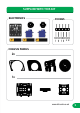
SUPPLIED WITH THIS KIT ELECTRONICS FIXINGS CHASSIS PANELS 2x 1x 4 www.kitronik.co.
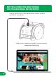
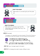
GETTING CONNECTED AND FINDING THE PROGRAMMING ENVIRONMENT Using a USB to micro-USB type B cable, connect the BBC micro:bit to a computer. Code will be created on the BBC micro:bit website. www.microbit.
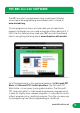
THE BBC micro:bit SOFTWARE The BBC micro:bit is programmed using a web based (internet access required) programming environment which is found at www.microbit.org. To save programs to access at a later date you will need to be logged in (although you can create a program without doing this). If this is the first time you have used your BBC micro:bit then please refer to our getting started guide at www.kitronik.co.uk/microbit.
GETTING A PROGRAM GETTINGON A PROGRAM ON TO THE BBC MICRO:BIT TO THE BBC GETTING A PROGRAM ON MICRO:BIT TO THE BBC MICRO:BIT It is very easy to transfer a finished program to the BBC micro:bit. ‘download’ . This is‘download’ where the program. This is. This converted into format that the BBC into a format that th ‘download’ is where the aprogram is converted First of all select is where the program is converted into a program the micro:bit can understand.
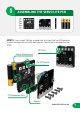
1 ASSEMBLING THE SERVO:LITE PCB Micro:bit sold separately STEP 1: Use a small Phillips screwdriver to screw the five M3 machine screws through the micro:bit and spacer, into the nuts mounted on the PCB. ZIP LEDs Servo Connections On/Off Switch PCB Mounted Nuts Spacer www.kitronik.co.
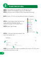
2 FLASH THE ZIP LEDs STEP 1: Put batteries into the SERVO:LITE PCB, and turn it on. STEP 2: Connect it to a computer using a micro-USB cable. STEP 3: Bring up Javascript Blocks Editor (makecode.microbit.org). NOTE: Kitronik’s ZIP LEDs are compatible with Adafruit’s Neopixels. STEP 4: In the toolbox towards the left of the screen, select the ‘Advanced’ section. Additional packages should appear below. STEP 5: Select ‘Add Package’. STEP 6: In the search bar type ‘neopixel’, then select the ‘neopixel’ box.
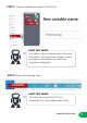
STEP 7: Create a variable and name it ‘Pixel Array’. WHAT THIS MEANS A variable is like a container which can store information. This could be a number, a word or a piece of information you want your program to remember. STEP 8: Create the following code. WHAT THIS MEANS This tells the micro:bit that Pin 0 is connected to 5, colour addressable LEDs. www.kitronik.co.
WHAT THIS MEANS When button A is pressed, light up all the pixels red. WHAT THIS MEANS When button B is pressed, clear the LED’s represented by the variable ‘Pixel Array’. This will turn them off. STEP 9: Download! The program will automatically run on the simulator. Click on the ‘A’ button on the simulator to see the LED pattern. Click on ‘B’ button to clear the pattern.
As well as addressing all the pixels at once it is possible to set them individually, or as a group. The first pixel always has an address of 0 (see diagram below). 0 1 2 3 4 STEP 12: Change the code under ‘On button A pressed’ to the following. NOTE: You may need to click on ‘More’ under the ‘neopixel’ toolset to view extra blocks. WHAT THIS MEANS Set the first two pixels to red, the middle pixel to white and the last two to blue. REMEMBER: To show a change you must use a block with ‘show’ in it.
STEP 15: Create the code below. WHAT THIS MEANS This code shows a colour changing pattern when button A is pressed and stops when button B is pressed. NOTE: The ‘rotate pixels’ tool shifts each LED colour onto the next LED. When it reaches the end of the line, it goes back onto to the first LED.
3 BUILDING THE WHEELS 2x STEP 1: Screw the 2 larger screws from the servo packet, through the wheel and into the appropriate holes in the servo attachment. The centre of the horn and the centre of the wheel should be aligned. Press fit the wheel onto the servo and repeat for the opposite side. NOTE: The screws should go through the holes shown above in red. www.kitronik.co.
4 TESTING THE SERVOS SERVOS The continuous rotation servos used in the :MOVE mini are controlled in the same manner as normal remote control servos. These servos are controlled by a repeating pulse, whose width commands the servo to turn to a position. For a normal servo, position is measured from the output shaft and used to determine what angle the servo should stop at. NORMAL SERVO 0 DEGREES 90 DEGREES 180 DEGREES CONTINOUS ROTATION A continous rotation servo is slightly different.
STEP 1: Plug the servos into the SERVO:LITE board. The :MOVE board connections are: TOP : GROUND : BROWN MIDDLE : POWER : RED BOTTOM : SIGNAL : ORANGE STEP 2: With both wheel servos plugged in, it is time to write some test code. Set out the servos like below. This will allow trimming/calibration of the servos. This means they will stop and travel at the same speed when commanded. www.kitronik.co.
STEP 3: Bring up JavaScript Blocks Editor (pxt.microbit.org). STEP 4: Create the following code. When button A is pressed, both servos should turn anti-clockwise (looking from the wheel side). When button B is pressed both servos should turn clockwise (looking from the wheel side). When buttons A + B are pressed the servos should stop turning. If they do not then the centre point trimmer will need adjustment. On the bottom of the servo, there is a small hole. This is used to access the trimmer.
5 CALIBRATING THE SERVOS STEP 1: Press buttons A+B, Then with a small screwdriver (through the hole) gently move the centre point trimmer until the servo completely stops. There should also be no sound coming from the servos. TRIMMER STEP 2: Once the servos are calibrated unplug them from the board and detach the wheels from the servos. NOTE: The diagram below shows how the number of degrees set in the code relates to the speed of the servo. SPEED: STOP DEGREES: www.kitronik.co.
6 ASSEMBLING THE CHASSIS STEP 1: Slot the servo into the base plate with the shaft facing out, and the wires facing up. This should fit very tightly and may require some pressure to snap into place. STEP 2: Slot the side part over the top of the servo, ensuring the panel sits in front of blue plastic lip of the servo before securing it with a screw and nut. Then repeat for the opposite side. STEP 3: Snap the pen mounting plate in between the two vertical plates, just above the servo.
STEP 4: Slot the screws through the outer panel and into the green panel, then add a nut onto the end of each. Repeat for the opposite side. STEP 5: Attach to the chassis, slot the nut into the T-joint and tighten the screw. www.kitronik.co.
STEP 6: Repeat for the opposite side. STEP 7: Add a wheel (built earlier) and screw the smallest servo screw through the middle to secure it.
STEP 8: Repeat for the opposite side. The chassis is now complete. www.kitronik.co.
7 ATTACHING ELECTRONICS STEP 1: Plug the servo cables back into the SERVO:LITE board. The left servo should plug into the left-hand side of the :MOVE board and vice versa. The cables should be threaded down the gaps on either side as shown and any excess tucked under the pen mounting plate. STEP 2: Clip the SERVO:LITE board under the hooks on the inner side plates and slide it between the outer plates.
STEP 3: Push the SERVO:LITE board fully back inside the :MOVE mini. STEP 4: Secure the SERVO:LITE board and micro:bit with the :MOVE T-piece. STEP 5: Tidy up the cables by tucking them into the gaps in between the side panels. STEP 6: Excess wires can then be fed into the servo compartment at the rear. www.kitronik.co.
8 CODE :MOVE MINI TO MOVE DRIVE IN A STRAIGHT LINE STEP 1: Create this code. NOTE: If the move mini does not travel in a straight line then you can adjust the values to make the servos run at the same speed. You may also need to adjust the trimmer (see pg 17). WHAT THIS MEANS When button A is pressed, drive full speed forwards. When button B is pressed, drive full speed backwards.
DRAW A CIRCLE! STEP 3: Drop a marker through the designated hole on the pen mounting plate and create the code below. WHAT THIS MEANS Drive one servo at full speed, and the stop the other. This will cause the :MOVE mini to drive in a circle. STEP 4: Download Upload ADD SOME LIGHTS! STEP 5: Create the following code to give :MOVE mini a head-light or tail-light. www.kitronik.co.
9 DRAW A SHAPE USING JAVASCRIPT A square has four equal sides, and four 90 degree corners. Because there are four corners and four edges, it is worth writing control functions for turning and driving to do this, rather than writing the same code four times. STEP 1: In the JavaScript Blocks Editor, create the following variables. These are used to store some constants about the :MOVE mini.
STEP 2: Add the following code under the previous code. WHAT THIS MEANS Because we do not have position feedback from the 360 degree servos we have to use time and a knowledge of how fast the :MOVE mini is to make the turn accurately. STEP 3: Program button A to call this function like this: NOTE: There is a pause to allow you to move your hand before the :MOVE mini starts turning Use this code to fine tune the ‘NumberOfDegreesPerSec’ so that the :MOVE mini turns through 90 degrees.
STEP 4: Next make a function to cause the MOVE mini to drive forwards: WHAT THIS MEANS This code is very similar to the block code used earlier, but includes a timer to stop the :MOVE mini after a certain distance. STEP 5: Program button B to call this function like this: NOTE: If the :MOVE mini drives too far/not far enough, adjust the value of the ‘DistancePerSec’ variable made earlier. If you make it bigger it will drive for less distance.
Now we have the building blocks to make the :MOVE mini draw a shape. STEP 7: Change the code in the ‘onButtonPressed(Button.A, () ’ function to: WHAT THIS MEANS This will draw a basic four-sided shape, which if your turns are accurate, will be a square. YOUR TURN: Write code to make the MOVE mini turn right, and drive backwards. Then combine that code to draw other shapes/pictures. STEP 8: Download Upload www.kitronik.co.
10 GO ONLINE! For additional tutorials, resources and accessories scan the QR Code or visit; kitronik.co.uk/movemini Kitronik has created custom blocks for the JavaScript Block editor. Add the package from: https://github.
TROUBLESHOOTING If you are having issues with the :MOVE mini, try the steps below! THE SERVOS ARE MISBEHAVING - Is the orange servo wire at the bottom of the connector? - Check all connections are secure. - Are the screws holding the electronics together tight? - Review your code, are you outputting to the correct pin(s)? :MOVE MINI WON’T DRIVE IN A STRAIGHT LINE - You may need to recalibrate your servos (see page 17).
:MOVE The Kitronik :MOVE mini for the BBC micro:bit provides an introduction to robotics. The mini is a 2 wheeled robot, suitable for both remote control and autonomous operation. A range of add on boards can expand the capabilities to include more advanced functionality. The :MOVE mini board included in this pack can also be used in conjunction with a BBC micro:bit to build other movement based projects. Visit kitronik.co.uk/movemini for more details. ( ) RoHS 32 THIS IS NOT A TOY.