
Owner's Manual
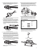
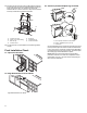
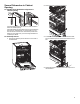
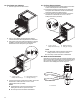
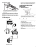
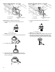
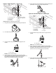
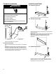
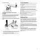
Table Of Contents
- DISHWASHER SAFETY
- Dishwasher Safety
- DISHWASHER MAINTENANCE AND CARE
- User-Maintenance Instructions
- INSTALLATION REQUIREMENTS
- Tools and Parts
- Location Requirements
- Cabinet Opening Dimensions
- Drain Requirements
- Water Supply Requirements
- Electrical Requirements
- INSTALLATION INSTRUCTIONS
- Before You Begin
- Prepare Cabinet Opening – New Utilities
- Install Moisture Barrier (Recommended for Wood Countertops)
- Prepare Dishwasher
- Remove Access and Toe Panels
- Connect Water Line to Fill Valve
- If a Drain Hose Extension is Required
- Install Door Handle (on some models)
- Place Dishwasher in Cabinet
- Custom Panel Installation (on some models)
- Electrical Connection
- Direct Wire Connection
- Power Cord Connection
- Junction Box Assembly
- Final Installation Check
- Secure Dishwasher in Cabinet Opening
- Choose Anchor Attachment Method
- Connect Water Line to House Shutoff Valve
- Connect Drain Hose
- Complete Installation
- Install Access Panel
- T-Gasket Installation (on some models)
- Check Operation
- If Dishwasher Does Not Operate
- Additional Tips
- SÉCURITÉ DU LAVE-VAISSELLE
- Sécurité du lave-vaisselle
- ENTRETIEN ET RÉPARATION DU LAVE-VAISSELLE
- Instructions d’entretien par l’utilisateur
- EXIGENCES D’INSTALLATION
- Outils et pièces
- Exigences d’emplacement
- Dimensions de l’ouverture de l’armoire
- Exigences d’évacuation
- Spécifications de l’alimentation en eau
- Spécifications électriques
- INSTRUCTIONS D’INSTALLATION
- Avant de commencer
- Préparation de l’emplacement – nouveaux appareils
- Installation de la barrière anti-humidité (recommandée pour les comptoirs en bois)
- Préparation du lave-vaisselle
- Retrait du panneau d’accès et de la plinthe
- Branchement de l’arrivée d’eau à la valve de distribution
- Si une rallonge de tuyau de vidange est nécessaire
- Installation de la poignée de porte (sur certains modèles)
- Placer le lave-vaisselle dans l’armoire
- Installation du panneau personnalisé (sur certains modèles)
- Raccordement électrique
- Méthode de raccordement direct
- Branchement du câble d’alimentation
- Boîtier de raccordement électrique
- Vérification finale de l’installation
- Fixation du lave-vaisselle dans l’ouverture d’encastrement de l’armoire
- Choix de l’option de fixation
- Branchement de l’arrivée d’eau au robinet d’arrêt de la maison
- Raccordement du tuyau de vidange
- Achever l’installation
- Installation du panneau d’accès
- Installation du joint en T (sur certains modèles)
- Vérification du fonctionnement
- Si le lave-vaisselle ne fonctionne pas
- Conseils supplémentaires

21
6. Attach one cable fitting to the junction box cable from the
dishwasher paying thorough attention to the orientation (see
below figure). The cable fitting shall tighten against the
secondary insulation (PVC jacket).
A
A. 0.25" (6.35 mm) minimum
Use wrench and/or pliers to fully tighten the elongated (strain
relief) nut against the strain relief body.
7. For Direct (home) wire connection (12-2/14-2 non-metallic
sheathed/Romex), Strip jacket insulation of the home wire to
expose the wires to the length of 5
1
/
16
" (129.3 mm) as shown
below. Strip each wire end by 0.75" (19 mm). Attach the
second cable fitting to home wiring paying attention to the
orientation (see below figure). Use wrench and/or pliers to
fully tighten the elongated (strain relief) nut against the strain
relief body.
B
A
C
A. 3
3
/
4
" (95 mm)
B. 0.75" (19 mm)
C. 0.25" (6.35 mm) minimum
8. For Direct (home) wire connection using armored cable or
flexible metal conduit use only a UL/CSA-approved metallic
strain relief for the type of conduit being used. Ensure 4"
(101.6 mm) of wire is extending out past the end of the strain
relief. Strip each wire end by 0.75" (19 mm). Attach the strain
relief to the home wiring per the strain relief manufacturer’s
instructions. Attach strain relief to the box per the strain relief
manufacturer’s installation instructions.
9. For power cord connection, attach the second cable fitting to
the power cord paying attention to the orientation (see below
figure). Use wrench and/or pliers to fully tighten the elongated
(strain relief) nut against the strain relief body.
A
A. 0.25" (6.35 mm) minimum
NOTE: Non-metallic sheathed wire is for direct wire
connection only.
10. Route wire ends into the junction box through the round holes
on the sides. Securely attach the cable fittings to the junction
box using plastic mounting nuts supplied with the cable
fittings. Hand tighten the mounting nuts to the cable fittings
and then use a crescent wrench to tighten another 1/4 turn.
Use a second wrench or pliers to secure the cable fitting body
when tightening the mounting nut.
11. Connect wires together inside the junction box using the
supplied wire nuts. Connect wires of the same color together
(black to black, white to white, and bare/green to green).
NOTE: Do not pre-twist wires before making connections.
Wiring configuration
Home Wire or
Power Cord
Junction Box
Cable
white
white
black
black
bare/green
green
12. To apply a wire nut, hold the stripped/bare ends of wires
parallel to each other with their ends aligned. Firmly push
wires into a wire nut and twist clockwise until secure (the
insulated wires outside the connector begin to twist). Gently
tug on each wire making sure they are secure.