
Owner's Manual
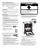
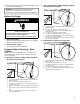
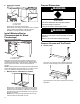
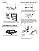
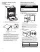
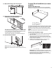
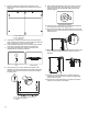
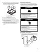
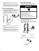
Table Of Contents
- DISHWASHER SAFETY
- Dishwasher Safety
- DISHWASHER MAINTENANCE AND CARE
- User-Maintenance Instructions
- INSTALLATION REQUIREMENTS
- Tools and Parts
- Location Requirements
- Cabinet Opening Dimensions
- Drain Requirements
- Water Supply Requirements
- Electrical Requirements
- INSTALLATION INSTRUCTIONS
- Before You Begin
- Prepare Cabinet Opening – New Utilities
- Install Moisture Barrier (Recommended for Wood Countertops)
- Prepare Dishwasher
- Remove Access and Toe Panels
- Connect Water Line to Fill Valve
- If a Drain Hose Extension is Required
- Install Door Handle (on some models)
- Place Dishwasher in Cabinet
- Custom Panel Installation (on some models)
- Electrical Connection
- Direct Wire Connection
- Power Cord Connection
- Junction Box Assembly
- Final Installation Check
- Secure Dishwasher in Cabinet Opening
- Choose Anchor Attachment Method
- Connect Water Line to House Shutoff Valve
- Connect Drain Hose
- Complete Installation
- Install Access Panel
- T-Gasket Installation (on some models)
- Check Operation
- If Dishwasher Does Not Operate
- Additional Tips
- SÉCURITÉ DU LAVE-VAISSELLE
- Sécurité du lave-vaisselle
- ENTRETIEN ET RÉPARATION DU LAVE-VAISSELLE
- Instructions d’entretien par l’utilisateur
- EXIGENCES D’INSTALLATION
- Outils et pièces
- Exigences d’emplacement
- Dimensions de l’ouverture de l’armoire
- Exigences d’évacuation
- Spécifications de l’alimentation en eau
- Spécifications électriques
- INSTRUCTIONS D’INSTALLATION
- Avant de commencer
- Préparation de l’emplacement – nouveaux appareils
- Installation de la barrière anti-humidité (recommandée pour les comptoirs en bois)
- Préparation du lave-vaisselle
- Retrait du panneau d’accès et de la plinthe
- Branchement de l’arrivée d’eau à la valve de distribution
- Si une rallonge de tuyau de vidange est nécessaire
- Installation de la poignée de porte (sur certains modèles)
- Placer le lave-vaisselle dans l’armoire
- Installation du panneau personnalisé (sur certains modèles)
- Raccordement électrique
- Méthode de raccordement direct
- Branchement du câble d’alimentation
- Boîtier de raccordement électrique
- Vérification finale de l’installation
- Fixation du lave-vaisselle dans l’ouverture d’encastrement de l’armoire
- Choix de l’option de fixation
- Branchement de l’arrivée d’eau au robinet d’arrêt de la maison
- Raccordement du tuyau de vidange
- Achever l’installation
- Installation du panneau d’accès
- Installation du joint en T (sur certains modèles)
- Vérification du fonctionnement
- Si le lave-vaisselle ne fonctionne pas
- Conseils supplémentaires

17
18. Move Dishwasher into final position
19. Place foam insulation pad below the
dishwasher (on some models)
After pushing the dishwasher in the cabinet opening, adjust
the leveling feet to standard height of 33
7
/
8
" (860 mm) and
up. Then take the floor insulation pad and slide it from the
front (gap between the floor & the drip tray).
The floor pad is designed to go around the leveling legs.
20. Pull slack from utilities
NOTE: Pull slack out of utilities at the same time the
dishwasher is pushed into the cabinet opening to avoid any
kinks.
Custom Panel Installation (on some
models)
Custom Panel Dimension
Make sure that the custom panel is as per the recommended
dimensions. See below image for the recommended dimensions.
A
B
C
A. 23
9
/
16
" (598 mm)
B. 28
3
/
8
"-30" (720-762 mm)
C. 5/8"-1" (16-25 mm)
A customer supplied door panel must weigh no more than 16 lbs
(7.3 kg) with the handle (together). And must be made to specific
dimensions as given above. It is recommended that a cabinet
maker cut the custom panel because of the precise dimensions
needed.
NOTE: The handle for the custom panel is not included.
Custom Panel Installation steps
1. In an area that is flat and clear of debris, place down a blanket
as a work surface.
2. Attach the custom panel handle as you would any other
cabinet handle. Be sure to protect the finished surface with
painters tape when preparing and recessing the rear panel to
conceal attachment hardware.
3. Install the custom hardware handle(s) on the front of the
custom panel, inside dotted line as shown below
A
A. 6" (152.4 mm)
IMPORTANT: If the handle is attached from the back of the
custom panel, the screw holes should be countersunk for the
screw heads to be flush with the panel. If the handle is
attached to the front of the custom panel, the screw lengths
cannot exceed the panel thickness.