
Owner's Manual
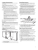
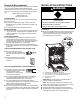
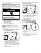
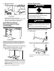
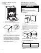
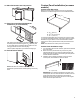
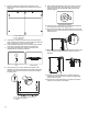
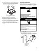
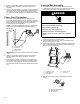
Table Of Contents
- DISHWASHER SAFETY
- Dishwasher Safety
- DISHWASHER MAINTENANCE AND CARE
- User-Maintenance Instructions
- INSTALLATION REQUIREMENTS
- Tools and Parts
- Location Requirements
- Cabinet Opening Dimensions
- Drain Requirements
- Water Supply Requirements
- Electrical Requirements
- INSTALLATION INSTRUCTIONS
- Before You Begin
- Prepare Cabinet Opening – New Utilities
- Install Moisture Barrier (Recommended for Wood Countertops)
- Prepare Dishwasher
- Remove Access and Toe Panels
- Connect Water Line to Fill Valve
- If a Drain Hose Extension is Required
- Install Door Handle (on some models)
- Place Dishwasher in Cabinet
- Custom Panel Installation (on some models)
- Electrical Connection
- Direct Wire Connection
- Power Cord Connection
- Junction Box Assembly
- Final Installation Check
- Secure Dishwasher in Cabinet Opening
- Choose Anchor Attachment Method
- Connect Water Line to House Shutoff Valve
- Connect Drain Hose
- Complete Installation
- Install Access Panel
- T-Gasket Installation (on some models)
- Check Operation
- If Dishwasher Does Not Operate
- Additional Tips
- SÉCURITÉ DU LAVE-VAISSELLE
- Sécurité du lave-vaisselle
- ENTRETIEN ET RÉPARATION DU LAVE-VAISSELLE
- Instructions d’entretien par l’utilisateur
- EXIGENCES D’INSTALLATION
- Outils et pièces
- Exigences d’emplacement
- Dimensions de l’ouverture de l’armoire
- Exigences d’évacuation
- Spécifications de l’alimentation en eau
- Spécifications électriques
- INSTRUCTIONS D’INSTALLATION
- Avant de commencer
- Préparation de l’emplacement – nouveaux appareils
- Installation de la barrière anti-humidité (recommandée pour les comptoirs en bois)
- Préparation du lave-vaisselle
- Retrait du panneau d’accès et de la plinthe
- Branchement de l’arrivée d’eau à la valve de distribution
- Si une rallonge de tuyau de vidange est nécessaire
- Installation de la poignée de porte (sur certains modèles)
- Placer le lave-vaisselle dans l’armoire
- Installation du panneau personnalisé (sur certains modèles)
- Raccordement électrique
- Méthode de raccordement direct
- Branchement du câble d’alimentation
- Boîtier de raccordement électrique
- Vérification finale de l’installation
- Fixation du lave-vaisselle dans l’ouverture d’encastrement de l’armoire
- Choix de l’option de fixation
- Branchement de l’arrivée d’eau au robinet d’arrêt de la maison
- Raccordement du tuyau de vidange
- Achever l’installation
- Installation du panneau d’accès
- Installation du joint en T (sur certains modèles)
- Vérification du fonctionnement
- Si le lave-vaisselle ne fonctionne pas
- Conseils supplémentaires

13
� Be sure when installing or moving the appliance that the power
cord is not kinked or damaged.
WARNING: To reduce the risk of electric shock, fire, or
injury to persons, the installer must ensure that the
dishwasher is completely enclosed at the time of installation.
Before You Begin
WARNING
Electrical Shock Hazard
Disconnect electrical power at the fuse box or circuit
breaker box before installing appliance.
Failure to do so can result in death or electrical shock.
1. Disconnect power
Disconnect electrical power at the fuse box or circuit breaker
box before installing dishwasher.
2. Shut off water supply
Shut off water supply to the dishwasher.
Prepare Cabinet Opening – New
Utilities
NOTE: The electric and water holes may or may not be on the
same cabinet wall. It will depend on the location of water and
electric connections.
3. Drill hole location for Water Supply and Drain
hose (Preferred hole type)
D
A
E
D
C
B
F
A. 6" (152 mm), minimum height of allowable area from bottom for
utility connections.
B. 1/2" (12.7 mm), Thickness of back cabinet wall.
C. 2
1
/
4
" width x 6
1
/
16
" height (57.20 x 154.40 mm), Allowable area
for utility connections.
D. 1
3
/
4
" (44.4 mm), Diameter of Oval hole for water supply and drain
hose.
E. 3
3
/
4
" (95.3 mm), Height of Oval hole for water supply and drain
hose.
F. 2
1
/
4
" (57.1 mm), Distance between center of Oval hole to the
back of the cabinet wall.
4. Drill hole locations for Water Supply and Drain
hose (Optional hole type)
A
E
D
E
B
C
D
F
G
A. 6" (152 mm), minimum height of allowable area from bottom for
utility connections.
B. 1/2" (12.7 mm), Thickness of back cabinet wall.
C. 3
1
/
2
" width x 6" height (88.9 x 152.4 mm), Allowable area for
utility connections.
D. 1
1
/
2
" (38.1 mm), Diameter for drain hose hole.
E. 3
1
/
2
" (88.9 mm), Diameter for water supply hose hole.
F. 2
1
/
4
" (57.1 mm), Distance between center of water supply hose
hole to the back of the cabinet wall.
G. 1
1
/
4
" (31.7 mm), Distance between center of Drain hose hole to
the back of the cabinet wall.
5. Drill location for Electrical conduit hole
D
A
B
C
D
E
A. 6" (152 mm), minimum height of allowable area from bottom for
utility connections.
B. 1/2" (12.7 mm), Thickness of back cabinet wall.
C. 1
1
/
2
" width x 12" height (38.1 x 304.8 mm), Allowable area for
utility connections.
D. 1
1
/
2
" (38.1 mm), Diameter for Electrical conduit hole.
E. 1
1
/
4
" (31.7 mm), Distance between center of Electrical conduit
hole to the back of the cabinet wall.