
Blender User Manual


BLENDER SERVICE MANUAL
8
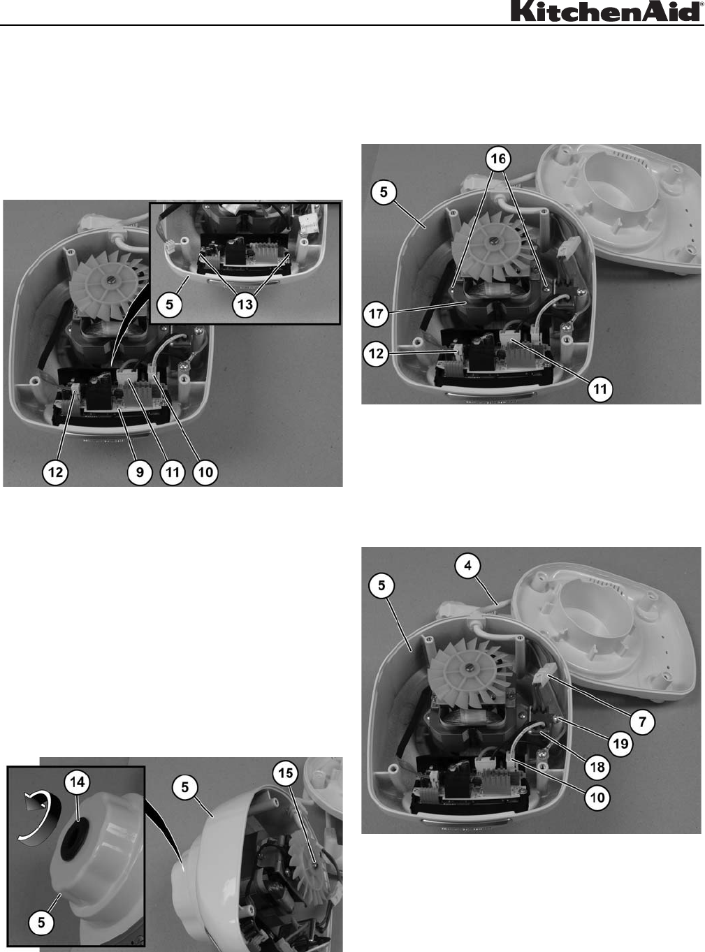
Electronic Speed Control
Board Replacement (Fig. 11)
To replace the electronic speed control board (9),
disconnect filter connector (10), motor connector (11),
and hall effect connector (12) from the electronic speed
control board (9).
Using a flathead screwdriver, press tabs (13) on
each side of control board (9) to remove from upper
housing (5).
Figure 11
To install the control board (9), snap into upper
housing (5) and connect all connectors.
Coupler Replacement (Fig. 12)
The coupler (14), in the upper housing (5), can be
removed by using a flathead screwdriver and a large
pair of pliers. Place the screwdriver in the slot of the
motor shaft (15). Hold the coupler (14) with the pliers.
Turn the shaft clockwise to remove the coupler.
The coupler (14) is threaded in a left-hand manner on
the end of the motor shaft. To install a new coupler, you
will use a counterclockwise rotation. Avoid damage to
the new coupler when installing by placing tape over
the jaws of the pliers.
Figure 12
Motor Replacement (Fig. 13)
After the coupler (14) has been removed, disconnect
the motor connector (11) and the hall effect
connector (12) from the control board (9). Remove the
two Phillips screws (16) and motor (17) from the upper
housing (5).
Figure 13
EMI Filter Replacement (Fig. 14)
To remove the EMI filter (18), disconnect connector (7)
from the power cord (4) and disconnect connector (10)
from the electronic speed control board (9). Remove
a Phillips screw (19) and EMI filter (18) from the upper
housing (5).
Figure 14