ORB180213 Rev.
ORBTM 4-20 mA Input Box Installation & Operation Manual CONTENTS I. HANDLING & STORAGE......................................................................................................................... 1 Inspection and Handling Disposal and Recycling Storage II. GENERAL SAFETY................................................................................................................................. 2 Authorized Personnel Use Misuse III. PRODUCT DESCRIPTION.......................
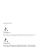
SAFETY SYMBOLS WARNING: IDENTIFIES CONDITIONS OR PROCEDURES, WHICH IF NOT FOLLOWED, COULD RESULT IN SERIOUS INJURY. RISK OF ELECTRICAL SHOCK. CAUTION: IDENTIFIES CONDITIONS OR PROCEDURES, WHICH IF NOT FOLLOWED, COULD RESULT IN SERIOUS DAMAGE OR FAILURE OF THE EQUIPMENT.
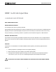
www.kistlermorse.com ORB 4-20 mA Input Box TM I. HANDLING AND STORAGE SAVE THESE INSTRUCTIONS INSPECTION AND HANDLING Do not dispose of the carton or packing materials. Each package should be inspected upon receipt for damage that may have occurred due to mishandling during shipping. If the unit is received damaged, notify the carrier or the factory for instructions. Failure to do so may void your warranty. If you have any problems or questions, consult Customer Support at 1-800-426-9010.
www.kistlermorse.com II. GENERAL SAFETY AUTHORIZED PERSONNEL All instructions described in the document must be performed by authorized and qualified service personnel only. Before installing the unit, please read these instructions and familiarize yourself with the requirements and functions of the device. The required personal protective equipment must always be worn when servicing this device. USE The device is solely intended for use as described in this manual.
www.kistlermorse.com III. PRODUCT DESCRIPTION FUNCTION The ORB™ 4-20 mA Input Box promotes communication from the 4-20 mA devices and transforms the data to a serial RS-422 communication for interfacing with other instruments and management equipment. The 4-20 mA Input Box enhances the communication ability of all the measuring and weighing devices as well as other devices such as temperature and moisture sensors.
www.kistlermorse.com IV. Mechanical Installation WARNING: REMOVE POWER FROM THE UNIT BEFORE INSTALLING REMOVING OR MAKING ADJUSTMENTS. CAUTION: Do not route serial cables in the same conduit with AC power cables. Notes: 1. Mounting hardware is not supplied by factory 2. When mounting the 4-20 mA Input Box ensure there is enough clearance to open the front door completely. Removal, insertion, and wiring of the modular PCB is done through the front of the unit.
www.kistlermorse.com V. ELECTRICAL INSTALLATION WARNING: REMOVE POWER FROM THE UNIT BEFORE INSTALLING, REMOVING OR MAKING ADJUSTMENTS GENERAL SAFETY When using electrical equipment, you should always follow basic safety precautions, including the following: • The installation/wiring of this product must comply with all national, federal, state, municipal, and local codes that apply. • Properly ground the enclosure to an adequate earth ground. • Do not modify any factory wiring.
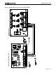
www.kistlermorse.com 4-20 mA Input Box Board Layout ORB Board Layout Figure 2. Standard Wiring from 4-20 mA Input Box to ORB 6 ORB180213 Rev.
www.kistlermorse.com Figure 3. Board Configurations ORB180213 Rev.
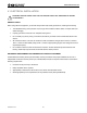
www.kistlermorse.com VI. SET-UP For the 4-20 mA Input Box to be set up, current count values for two different tank volumes must be known or recorded. The values can be determined by: • Using the values provided by the factory • Using the ORB to obtain a current reading of the device TO OBTAIN A CURRENT COUNT READING – FOR ORB SOFTWARE VERSION 2.3 1. Log into the ORB normally 2. Choose Manage Devices 3. Click on one of the 4-20 mA names listed 4. Click ‘Get Current ADC Value’ 5.
www.kistlermorse.com TO OBTAIN A CURRENT COUNT READING – FOR EARLIER ORB SOFTWARE VERSIONS 1. Log into the ORB normally 2. Click ‘Realtime View’ from the left side navigation on the Main Menu screen 3. Verify that the time value is five (5) seconds or less. 4. Record the ADC value and the weight or level of the material in the vessel. 5. Click Main Menu 6. Add or remove material from the vessel 7. Click ‘Realtime View’ from the left side navigation on the Main Menu screen 8.
www.kistlermorse.com VII. MAINTENANCE PREVENTATIVE There are no preventative maintenance actions required for this product. REPLACEMENT PARTS PART NUMBER DESCRIPTION SPK-ORB420-01 4-Channel Input Board with Mounting Hardware VIII. troubleshooting For technical or service questions, please call the manufacturer. 10 ORB180213 Rev.
www.kistlermorse.com IX. Dimensional Drawings ORB180213 Rev.
150 Venture Boulevard Spartanburg, SC 29306 Tel: (800) 426-9010 Tel: (864) 574-2763 [Local] Fax: (864) 574-8063 sales@kistlermorse.com www.kistlermorse.com 2013 All rights reserved. All data subject to change without notice. ORB180213 Rev.