
Instruction Manual


7
www.kistlermorse.com
97-1100-01 Rev. H
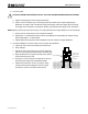
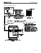
CAUTION: IF INSTALLING SHIMS, LOOSEN THE TOP BOLTS ON ALL THE LOAD STANDS BEFORE
RAISING THE VESSEL.
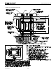
RubberWasher
FromKistler-Morse
VesselLegand
MountingPlate
Bolt
CenterLoadStand
topmountingholes
withvesselmounting
holes.Centerboltsin
mountingholes.
(Boltsandholesshown
forclarity.)
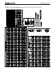
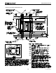
RubberPad
FromKistler-Morse
RubberWasher
FromKistler-Morse
Nut
RubberPad
FromKistler-Morse
JunctionBox
Leave1/4in.
(6mm)Gap
Minimum2in.
(51mm)forGrout
Nut
Washer
LevelingNut
andWasher
Grout:
Notinstalled
untilaftervessel
isleveled.
VessselMountingSurface
Nomorethan
minimumof±1º
or1/4in.(6mm)
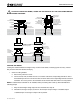
LEVELING THE VESSEL
Leveling the vessel distributes the weight evenly on all the Load Stands, increasing system accuracy. Perform
this procedure while the vessel is still empty:
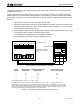
1. Check if Leveling Needed
a. Remove the junction box cover.
b.
Connect the red, white, and black wires of a 3-conductor cable to the corresponding terminals on TB1 of
the Load Stand junction box. Connect the other end of the cable to the corresponding terminals of the K-M
T
est Meter. Turn on the power to the Test Meter and set the Simulate/Test switch to the Test position.
NOTE: If a Kistler-Morse Test Meter is not available, before proceeding refer to Set-Up; Alternate Method for
Checking Output.
c. Verify the dead weight voltage output of the Load Stand from step 3f.
d. Calculate the change in output, as shown in the example. Output Change = uninstalled output
- installed output. The change in output must be positive.