97-1100-01 Rev.
Load Stand® II Installation & Operation Manual CONTENTS I. Handling And Storage................................................................................................................ 1 Inspection And Handling Disposal And Recycling Storage Ii. General Safety.............................................................................................................................. 2 Authorized Personnel Use Misuse Iii. Product Description..........................................................
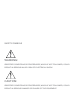
SAFETY SYMBOLS WARNING: IDENTIFIES CONDITIONS OR PROCEDURES, WHICH IF NOT FOLLOWED, COULD RESULT IN SERIOUS INJURY. RISK OF ELECTRICAL SHOCK. CAUTION: IDENTIFIES CONDITIONS OR PROCEDURES, WHICH IF NOT FOLLOWED, COULD RESULT IN SERIOUS DAMAGE OR FAILURE OF THE EQUIPMENT.
www.kistlermorse.com Load Stand® II Installation & Operation Manual I. HANDLING AND STORAGE Save these instructions INSPECTION AND HANDLING Do not dispose of the carton or packing materials. Each package should be inspected upon receipt for damage that may have occurred due to mishandling during shipping. If the unit is received damaged, notify the carrier or the factory for instructions. Failure to do so may void your warranty.
www.kistlermorse.com II. GENERAL SAFETY AUTHORIZED PERSONNEL All instructions described in the document must be performed by authorized and qualified service personnel only. Before installing the unit, please read these instructions and familiarize yourself with the requirements and functions of the device. The required personal protective equipment must always be worn when servicing this device. USE The device is solely intended for use as described in this manual.
www.kistlermorse.com III. PRODUCT DESCRIPTION FUNCTION The Kistler-Morse Load Stand® II is a direct vessel-to-foundation structural member designed to be your dependable and accurate continuous inventory monitoring and control solution. The Load Stand II system is ideal for vessels with loads of 100,000 lbs (45,000 kg) or more and is available for loads of 25,000 to 1,000,000 lbs (11,000 to 453,000 kg) per support point.
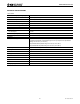
www.kistlermorse.com TECHNICAL SPECIFICATIONS FUNCTIONAL Excitation Voltage - Operating Range 12 VDC - 30 VDC Current Draw 15.52 mA (70º F, 21º C) Power Consumption 186.4 mW (70º F, 21º C) at 12 VDC excitation UBC Allowed Frame and Bolt Loads Refer to Table Ultimate Frame and Bolt Design Strength Refer to Table Sensor Functional Integrity 200% of rated load PERFORMANCE Rated Output 320 mV or 26.6 mV/V @ 12 V Excitation No Load Output ± 50 mV Non-Linearity & Hysteresis ± 0.
www.kistlermorse.com IV. mechanical INSTALLATION WARNING: REMOVE POWER FROM THE UNIT BEFORE INSTALLING, REMOVING, OR MAKING ADJUSTMENTS. VESSEL PREPARATION There are two aspects to successful use of Load Stands — properly functioning Load Stands and appropriate vessel support characteristics. Review the following list of error sources, and make the recommended corrections before you install Load Stands: • An inadequate vessel foundation can allow excessive movement.
www.kistlermorse.com INSTALLATION Warning: Use proper supports to prevent the vessel from tipping or falling. 1. Raise the vessel. 2. Inspect the bottom of the vessel mounting surface to ensure it is perfectly flat. Check for angular misalignment. Remove any debris from the mounting surface. 3. Mount the Load Stands on the foundation. a. Place the customer-supplied leveling nut and hardened washer on each anchor bolt. Check the angular alignment. b.
www.kistlermorse.com caution: If installing shims, loosen the top bolts on all the Load Stands before raising the vessel. Vessel Leg and Mounting Plate Bolt Rubber Washer From Kistler-Morse Rubber Pad From Kistler-Morse Center Load Stand top mounting holes with vessel mounting holes. Center bolts in mounting holes. (Bolts and holes shown for clarity.) Rubber Pad From Kistler-Morse Junction Box Leave 1/4 in.
www.kistlermorse.com • Check the wiring polarity at the K-M Test Meter. Ensure the red, white, and black wires are connected to the corresponding terminals. • If the wiring is correct and you still observe a negative output change, the vessel may be tilted. Vessel tilting shifts the load onto some Load Stands while putting other Load Stand(s) in a no load or tension load condition. This can occur in cases of extreme thermal deformation or unequal vessel leg length. Proceed to Step 2 to level the vessel. e.
www.kistlermorse.com 2. Level the vessel. caution: Loosen the top bolts on all the Load Stands before raising the vessel. a. Raise the vessel legs for the low output load stands. b. Raise or lower the leveling nuts or add shim(s) above the rubber pad as required adjusting the distribution of weight on the Load Stands. Raising the leveling nuts and/or adding shims increases the weight on the Load Stand. Lowering the leveling nuts decreases the weight on the Load Stand.
www.kistlermorse.com FIGURE 1: LOAD STAND DIMENSION CHART (For any note references, see Figure 2 or 3) 10 97-1100-01 Rev.
www.kistlermorse.com FIGURE 2: CONCRETE MOUNTING 97-1100-01 Rev.
www.kistlermorse.com FIGURE 3: SUPPORT BEAM MOUNTING 12 97-1100-01 Rev.
www.kistlermorse.com V. ELECTRICAL INSTALLATION WARNING: VERY HIGH VOLTAGE IS PRESENT. REMOVE POWER FROM THE UNIT BEFORE INSTALLING, REMOVING, OR MAKING ADJUSTMENTS GENERAL SAFETY When using electrical equipment, you should always follow basic safety precautions, including the following: • The installation and wiring of this product must comply with all national, federal, state, municipal, and local codes that apply. • Properly ground the enclosure to an adequate earth ground.
www.kistlermorse.com • Use Belden 3-conductor shielded interconnect cable or equivalent to wire junction boxes together and to the signal processor, for lengths up to 2,000’ (305 m) • When wiring cable to junction box terminals, strip back 3” (76 mm) of cable sheathing to expose the three conductor wires and shield wire inside. Strip 1/4” (6 mm) of insulation from the end of each of the conductor wires. Figure 3-7. Spread a generous bead of sealant around the sides of the PG 13.5 cable fittings.
www.kistlermorse.com FIGURE 4: SIGNAL CABLE LAYOUT 97-1100-01 Rev.
www.kistlermorse.com FIGURE 5: INTERCONNECT DIAGRAM 2 1. 2. 3. 4. 5. 6. 16 97-1100-01 Rev.
www.kistlermorse.com VI. SET-UP INSTALLING A SUN SHIELD The sun shield reduces sun-induced stresses in the Load Stand sensors and provides additional protection for the sensors. 1. With the junction box cover off, slightly loosen the screws attaching the junction box to the Load Stand. 2. Slightly loosen the horizontal screw(s) on the bottom flange of the Load Stand. 3. Wrap the sun shield around the Load Stand, slipping the cutout slots behind the loosened screws. 4.
www.kistlermorse.com calibration when scheduling permits you to move material into or out of the vessel. The following sections provide procedures for performing Live Load and Manual calibrations. Live Load Calibration Live Load calibration can be performed by adding or removing a known quantity of material from the vessel. The quantity of material moved must be at least 25% of the vessel’s total capacity. The procedures for both Live Load calibrations methods follow.
www.kistlermorse.com Manual Calibration Note: Kistler-Morse SVS 2000™ signal processor performs a manual calibration automatically, with Quick Config. 1. Refer to the signal processor manual to determine how to obtain the A/D converter sensitivity, expressed in Counts/mV. Record this value. 2. Record the Rated Load for one Load Stand. 3. Record the sensitivity (S) for your Load Stand. Load Stand II Sensitivity S2-025K, -075K, -150K, -200K, -300K, -400K, -500K, -750K, -1M, S2-050K, -100K 26.67 mV/V 4.
www.kistlermorse.com Scale Factor Counts = S x Excitation Voltage (V) x Counts/mV = 26.7 mV/V x 12 V x 699.05 Cnts/mV = 223,975 Counts Zero_Cal = current live load = 50,000 lbs Note: Some installations have ‘dummy’ Load Stands under one or more legs. This does not affect the manual calibration parameter calculation. Use the total number of supports, not the total number of Load Stands, in the calculation.
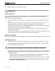
www.kistlermorse.com VII. Troubleshooting SYMPTOM POSSIBLE CAUSE SOLUTION Small Amplitude Changes or Erratic Fluctuations in Display Readings Fluctuations can be caused by small amplitude drift or oscillation, with peak-to-peak disturbance of 0.1% to 0.5% of full scale, is normal. Reduce drift or oscillation by setting ‘count by’ and ‘averaging’ appropriately on signal processor (refer to signal processor manual). Problem likely to be noticed shortly after initial installation.
www.kistlermorse.com SYMPTOM POSSIBLE CAUSE SOLUTION (Continued from previous page) (Continued from previous page) Problem likely to be noticed shortly after initial installation or on system that previously functioned correctly. 7. Identify damaged sensor at Load Stand identified in Step 3, 4, or 5: a. Remove one sensors’s wires from junction box terminal TB3. b. Put one DMM lead on sensor’s white wire and other lead on red wire. Record resistance, and verify it is 7,660 ± 200 ohms.
www.kistlermorse.com SYMPTOM POSSIBLE CAUSE SOLUTION Repeatable Drift over 24-hour Period Periodic drift is most likely caused by thermal expansion due to sun’s radiation or vessel’s response to its own heating cycles. Loosen nuts on top bolts and inspect top bolts. Problem likely to be noticed shortly after initial installation or on system that previously functioned correctly in cool or overcast weather. To reduce head radiation/conduction: a. Insulate vessel. b.
www.kistlermorse.com VIII. dimensional drawingS 24 97-1100-01 Rev.
www.kistlermorse.com NOTES 97-1100-01 Rev.
www.kistlermorse.com NOTES 26 97-1100-01 Rev.
www.kistlermorse.com NOTES 97-1100-01 Rev.
150 Venture Boulevard Spartanburg, SC 29306 Tel: (800) 426-9010 Tel: (864) 574-2763 [Local] Fax: (864) 574-8063 sales@kistlermorse.com www.kistlermorse.com 2014 All rights reserved. All data subject to change without notice. 97-7006-01 Rev.