
User guide


Chapter 3. LD3xi/LD3xiC Mounting
3-7
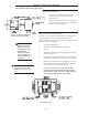
Mounting Junction Box
1. See Figure 3-6. Hold the junction box at the
desired mounting location. Mark the four
mounting holes.
2. Mount the junction box with #8-32 socket head
cap screws and flat washers per your application.
Tighten the screws until snug.
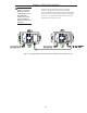
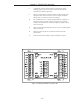
Wiring Load Discs to Junction Box
See Figure 3-7. The stainless steel junction box accommodates up
to eight Load Discs, with up to two Load Disc wires at each
terminal. Note that the junction box has no pre-cut holes for conduit
or fittings. Follow this procedure:
1. Install liquid tight fittings.
2. Seal fittings with Sikaflex™ or electrical grade
sealant.
3. Thread the Load Disc cable through the desired conduit
fitting. (See Figure 3-7).
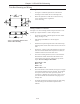
4. Estimate the required length of cable to the terminal strip,
allowing a little extra for strain relief. Cut the excess cable.
5. Strip back 3” (76mm) of the cable sheathing to expose the
four wires and the shield inside. Strip back
1
/4” (6mm) of
insulation from the end of each of the wires.
6. Connect the Load Disc wires to the selected TB2-5
terminals on the left side of the junction box: red or
brown wire to +EX, white wire to +SIG, and black
wire to -EX, and blue or yellow wire to -SIG.
Junction Box Mounting and Wiring
Figure 3-6: Plastic and Stainless
Steel Junction Box Mounting
Figure 3-7: Wiring Load Discs to Stainless
Steel Junction Box
Note: If you have a 61-6036-01
Stainless Steel J-Box with
trimming pots, refer to page
3-10.
CAUTION: Only use
Sikaflex™ 1A polyure-
thane sealant or Dow
Corning™ RTV 739 or
RTV 738. Other
sealants may contain
acetic acid, which is
harmful to sensors and
electronics.