
Product Manual


Page 12
• Connect another DC input cable between the other terminal of the fuse holder or DC rated circuit
breaker to the battery positive terminal.
Note: For Marine application, either the DC fuse or DC rated circuit breaker needs to be installed within 7 inches
(17.8cm) from the battery positive terminals.
• Install the selected fuse to the fuse holder.
Chassis DC Ground Connection:
• Connect the grounding wire to the unit’s Chassis DC Ground Lug located near the DC Input
terminal and the other side of the cable to the common grounding point.
• For a Recreation Vehicle, the common ground point is usually the vehicle chassis or a dedicated
DC ground bus.
• For Marine, the common ground point is usually the DC ground bus or engine negative bus.
Note: Do not use the Chassis DC Ground Lug for your AC Grounding, For AC Grounding, see AC Wiring
instructions for more details.
AC Input and AC Output Hardwire Connections:
Warning: Before making any AC Input and AC Output Hardwire connection, please be sure the AC
Input Source is not energized and the DC disconnect switch is switched OFF. Please double check
the location of the AC input connector located inside the wiring compartment. Misconnecting to the
AC output connector inside the same compartment will damage the unit and may cause fire.
Remove the AC compartment cover by unscrewing the four screws located at the front of the AC
compartment cover.
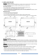
For AC Input Connections:
• Insert the AC Input cable through the AC Input Strain relief ○g on the unit.
• Connect the AC Main Panel AC Ground wire to the AC Input Ground terminal ○a on the unit. If a
solid ground wire is used, the wire can be connected directly under the screw head. If a stranded
ground wire is used, ring terminals must be used
• Connect the AC Main Panel AC Live or Hot wire to unit’s AC Input ‘L’ Live or ‘H’ Hot’ terminal ○b .
• Connect the AC Main Panel AC Neutral wire to unit’s AC Input Neutral ‘N’ terminal ○c .
• Tighten the strain relief to secure the AC Input wire.
For AC Output Hardwire Connections:
• Insert the AC Input cable through the AC Output Strain relief ○h on the unit.
• Connect the AC Sub-Panel AC Ground wire to the AC Output Ground terminal ○f on the unit. If a
solid ground wire is used, the wire can be connected directly under the screw head. If a stranded
ground wire is used, ring terminals must be used
• Connect the AC Sub-Panel AC Live or Hot wire to unit’s AC Output ‘L’ Live or ‘H’ Hot terminal ○d .
• Connect the AC Sub-Panel AC Neutral wire to unit’s AC Output Neutral ‘N’ terminal ○e .
• Tighten the strain relief to secure the AC Input wire.
Multi-Function Display Connection:
• Route the RJ12 cable from the unit to your desired location for the Multi-Function Display and
connect one end of the cable to the main unit Display Port and the other end of the cable to the
Display Panel socket located at the rear panel of the Multi-Function Display.