
User Manual
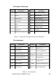


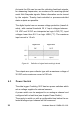

Description of the parts:
Number Description Number Description
1 USB
9
Module jack connection
2 Ethernet 10 LED ERR (red)
3 Voltage supply 11 LED RUN (green)
4 Power switch 12 Ethernet Link / Traffic
5 RS485 13 Press/rotary knob
6 RS232
14
8 analogue inputs
7 6 digital I/Os
15
LC-display
8 Status-LEDs for digital I/Os
16
Interface for memory card
Table 3.1 Description of the parts on the front of the device
Pin assignment:
Terminal Assignment Terminal Assignment
+10..30V Voltage supply + I/O + Digital I/O 1…6
0V Voltage supply - 0 V Ground for digital I/Os
A RS485-bus interface A SOURCE Source output
B RS485-bus interface B In+ Analogue input +
RX RS232 receive In- Analogue input -
TX RS232 transmit
AGND
Ground for analogue input
COM RS232 ground
UOUT 1 / 2
Power switch output
Table 3.2 Pin assignment
Hardware Manual COMBILOG 1022
21