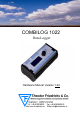
COMBILOG 1022 Data Logger Hardware Manual Version 1.
Issue: 22.01.
Copyright 1995-2010, Theodor Friedrichs & CO (Germany). Copyrights: Operating instructions, manuals and software are subject of copyright. Copying, duplication, translation, conversion into any electronic medium or any machine readable form, as a whole or in parts, is not permitted, with the exception of making a back-up copy of the software for saving purposes, insofar as this is technically feasible and is recommended by our company. Contraventions will lead to compensation.
Hardware Manual COMBILOG 1022
CHAPTER SURVEY Page 1 GENERAL PRELIMINARY REMARKS...............10 2 SYSTEM DESCRIPTION........................................12 3 INSTALLATION.......................................................19 4 SIGNAL PROCESSING..........................................28 5 FUNCTIONAL DESCRIPTION..............................34 6 DISPLAY / MENU OPERATION...........................60 7 DATA STORAGE.....................................................74 8 MASTER FUNCTION..............................
TABLE O F CO NTENTS Page 1 GENERAL PRELIMINARY REMARKS...............10 1.1 1.2 1.3 About this Manual....................................................................10 Important Notice......................................................................10 Contact for Inquiries................................................................11 2 SYSTEM DESCRIPTION........................................12 2.1 2.2 2.3 2.4 System Overview.............................................................
5 FUNCTIONAL DESCRIPTION..............................34 5.1 5.1.1 5.1.2 5.1.3 5.2 5.2.1 5.2.2 5.2.3 5.3 5.3.1 5.4 5.5 5.6 5.7 5.8 5.9 Analogue Input Channel..........................................................35 Voltage Measurement.............................................................36 Current Measurement..............................................................38 Resistance Measurement........................................................40 Digital Input Channel......................
9 INITIATION AND TEST..........................................84 9.1 9.2 9.3 Before Connecting the Device.................................................84 After Connecting the Device....................................................84 Configuration of the Data Logger............................................84 10 STRUCTURE OF THE BUS TOPOLOGY...........86 10.1 10.2 10.3 10.4 10.5 10.6 10.7 10.8 10.9 10.10 Bus Interface...........................................................................
11.11 Modem Connection...............................................................143 12 WEBSERVER.........................................................144 12.1 12.2 12.3 12.4 12.5 12.6 12.7 12.8 12.9 12.10 12.11 12.12 12.13 General..................................................................................144 System Info............................................................................144 System Log............................................................................
1 GENERAL PRELIMINARY REMARKS 1.1 About this Manual The manual contains all important information concerning the function, installation and initiation of the data logger COMBILOG 1022. The description of the configuration software for the COMBILOG-System is available as Online-Help within the configuration software COMBILOG.EXE. 1.
this manual, which only explains the general use of the data logger COMBILOG 1022. 1.3 Contact for Inquiries In case of inquiries concerning the data logger COMBILOG 1022 please contact your local distributor or directly Theodor Friedrichs & Co. GmbH.
2 SYSTEM DESCRIPTION 2.1 System Overview The COMBILOG 1022 is a data logger with compact design, combined with integrated LC-display and memory slot suitable for SD cards. This data logger was developed for meteorological, hydrological and environmental measuring systems, but it is equally suitable for countless further applications in industrial production. The COMBILOG 1022 features high performance, compact design (SMD components), low power consumption and moderate price.
For applications like outdoor use there is a version with stainless steel housing available, as well as various other accessories. Configuring of the data logger is accomplished by means of an easy to handle WINDOWSTM 98 / ME / NT / 2000 / XP software. 2.2 Range of Application As described under (2.1), the most varying measurement tasks can easily be accomplished by means of the COMBILOG 1022. Some typical applications are e.g.
logger via the RS485 bus. In this case the COMBILOG is used as a bus master to read the measured values from the slave modules. All data can be transmitted via the integrated RS485 communication interface to a subsequent control (PLC) or to a computer (PC). Up to 127 modules can be connected with the twowire line over distances of several km. At the same time the communication interface features programming and configuring the individual application from a PC.
2.3 Features Function: Measurement inputs for all common types of sensors for I, U and R.
LED-status indication for the ethernet interface LC-display (4 x 16 characters) and push-/turn knob for operation Measured value processing: Linearisation, scaling and conversion into physical units Option to adjust, modify or reset the processing parameters individually Master function to retrieve data from external modules Programmable averaging Automatic message transmission via modem or SMS Non-volatile storage for program, parameters and data Configuration: Configurable with PC-softwa
Communication: Integrated RS 485, RS 232, USB and Ethernet communication interface Autonomous function independent of subsequent systems Definition of the transmission protocol (ASCII and PROFIBUS or MODBUS) Definition of the telegram format (baudrate and parity) Definition of the output format (field length / decimals / unit) Simple instruction set Shell: Compact structural shape Attractive design Fast mounting Snap-on mounting on DIN rail 35 mm / 1.
In case a software update for the data logger is necessary, the configuration program provides a download function, that sends the new program to the logger. Communication is supported via standard interface (RS232), telephone or GSM modem or TCP/IP protocol.
3 INSTALLATION 3.1 Mounting / Fixing The data logger COMBILOG 1022 has a snap-on mounting for installation on standard profile rails 35 mm (1.4 inch) according to DIN EN 50022. Installation on the DIN rail is performed by means of the four straps on the rear side of the data logger. First push the two straps on the bottom behind the notch of the DIN rail and then press the data logger on the DIN rail until the two straps on the top snap in.
3.3 Ambient Temperature The admissible ambient temperature for the data logger COMBILOG 1022 is -45 °C to +85 °C. The admissible ambient temperature for the LC-Display is between -20°C and +60°C and becoming very slow below 0°C. Attention: For certain memory card types, differing temperature ranges have to be considered. 3.4 Front panel / Pin Assignment The front panel of the data logger COMBILOG 1022 shows following elements: 1 16 2 9 3 15 4 5 7 6 14 13 12 8 11 10 9 Figure 3.
Description of the parts: Number Description Number Description 1 USB 9 Module jack connection 2 Ethernet 10 LED ERR (red) 3 Voltage supply 11 LED RUN (green) 4 Power switch 12 Ethernet Link / Traffic 5 RS485 13 Press/rotary knob 6 RS232 14 8 analogue inputs 7 6 digital I/Os 15 LC-display 8 Status-LEDs for digital I/Os 16 Interface for memory card Table 3.1 Description of the parts on the front of the device Pin assignment: Terminal Assignment Terminal +10..
3.5 Connection Connection: Nominal cross section: Length of wire stripping : Alternatively available: Protection earth: plug-in screw terminals 1.5 mm² (0.02 square inch) unifilar/fine-strand (AWG 16) 6 mm (0.2 inch) LP-terminals (spring loaded) (upon request) 6.3mm series tabs at rear side of housing The best way to pull off the screw terminals is to use a small screwdriver, placed as a lever between terminal and the front of the data logger.
3.6 Power Supply U+ Versorgungsspannung Power Supply U- Figure 3.2 Connection of the distribution voltage Voltage range +10 ... +30 VDC Power input 0.1 W typical (up to 1.1W maximum, depending on configuration) Internal protector (reversible) excess current 0.
Non-regulated DC voltage between +10 and +30 VDC is sufficient for the power supply of the data logger COMBILOG 1022. The input is protected against excess voltage and current and against reverse polarity. The power consumption remains approximately constant over the total voltage range, due to the integrated switching controller. Due to its low current consumption (max. 110 mA at 12 VDC) the data logger can also be remote-fed via longer lines.
3.7 Bus Connection In general the data logger is connected to the bus by applying the signal leads A and B of the incoming bus cable and A' and B' of the outgoing bus cable together to one terminal on the module (figure 3.3). Alternatively the bus can also be connected by a "stub cable" as shown in figure 3.4. Owing to the removable terminal, the bus connection to other data loggers remains valid, even if one data logger is replaced by another. A B Figure 3.
A B Figure 3.4 3.8 Connection of the data logger to the bus by a stub cable Sensor Connection The analogue and digital signal inputs and outputs are wired according to measurement task, to the transducer (sensor) that is used, and to the number of connected sensors. The pinout arrangements for the various types of measurement are described in chapter 5. The respectively valid pin assignment is determined by means of the configuration software.
Following devices can be connected directly to the digital outputs: signal lamps, small relays, switching relays for larger loads, acoustic signal installations, buzzer respectively beeper etc., as long as the connected loads are not exceeding the values described in the technical data chapter 12. 3.9 Several Sensors at one Data Logger The data logger COMBILOG 1022 can simultaneously receive and process sensor signals from several different sensors.
Note: It is necessary to take care that the current at the Module Jack is not higher than permitted. Thus, the power supply preferably should be led to the centre of the module line. For the same reason a 100 mA self resettable fuse protects the module connector of the COMBILOG 1022 against short circuits. The permanent current drawn from the module connector shall not be higher than 100 mA.
4 SIGNAL PROCESSING The data logger COMBILOG 1022 has eight analogue inputs and six digital inputs/outputs. Several different sensor signals as well as digital inputs and digital output signals can be connected and processed simultaneously. 4.1 Analogue Inputs The analogue inputs serve to collect sensor signals, or to acquire control values respectively. They are particularly designed to measure voltages, currents and resistances.
As inputs the I/Os can be used for collecting feed-back signals, for measuring frequencies, as counters or for receiving special serial 8-bit-Graycode signals. Status information can be issued by the outputs. Thereby host-controlled or process-controlled status outputs are possible. The digital inputs have an excess voltage protection (transil diodes), with nominal threshold 30 V. Input voltages between 2.0 VDC and 30 DC are interpreted as logic LOW ("0"), input voltages lower than 0.
4.4 Internal Reference Voltage, Offset- and Drift Correction An internal reference voltage serves to adjust the entire analogue signal processing automatically. Especially for measurement of extreme low voltages, currents and resistances, the configuration software features an additional compensation of temperature drift. With current- and voltage measurement, this is realized by an internal offset measurement. The measured offset is subsequently applied to correct the measured values.
4.5 Internal Processing Next to collecting the analogue input signals, the analogue multiplexer at the input of the circuit collects the internal reference voltage. All these values are then transmitted to the programmable amplifier PGA, where the signals are amplified according to the kind and type of the connected sensors and then supplied to the A/D converter. The A/D converter digitalises all incoming signals with a definition of 16 bit and at a rate that can be preset for the module by the user.
failure or breaking of the sensing element or short-circuit can also be realised. The data logger can be activated - by means of appropriate configuration - to provide a corresponding signal at the digital I/O in case of alarm. The digital I/Os are directly addressed and monitored respectively by the microprocessor µP. Hereafter an arithmetical averaging of the values is carried out. The average interval is the same for each channel and is adjustable in steps of 0.
4.7 Signal Processing Arithmetical averaging is carried out using several measuring values. The averaging interval, which is the same for all channels, can be set to one of the values 0.5, 1, 2, 3, 4, 5, 10, 15, 20, 30 seconds or 1, 2, 3, 4, 5, 10, 15, 20, 30 minutes or 1, 2, 3, 4, 6, 8, 12 hours respectively. The calculated values are finally stored in the memory.
5 FUNCTIONAL DESCRIPTION The data logger COMBILOG 1022 has a total of 32 logical channels for the collection, processing and output of various kinds of sensor information. These 32 channels can be configured as: Analogue Input Channel Digital Input Channel Digital Output Channel Arithmetic Channel Setpoint Channel Alarm Channel For each channel various kinds of channel information and processing functions can be determined.
5.1 Analogue Input Channel The Analogue Input Channel collects and processes the signals of the most common types of sensors. A large number of standardised sensors is already stored in the COMBILOG internal sensor data base. Further sensors can be added by the user.
5.1.1 Voltage Measurement Two methods are available for voltage measurement: singleended and differential measurement. With the single-ended type the voltage to be measured is connected between an analogue input (In+) and analogue ground (AGND). Differential measurements are realized by using two analogue inputs (In+ and In-). Measuring range is between 0 and ±10 V. Note: With differential measurements both voltages have to be within 10 V referred to AGND (Common-Mode-Range).
Voltage Measurement Anschlussschema Connection scheme Schaltung Circuit Source IN+ + = U1 IN- - U AGND - + = U = U1 Figure 5.1 Voltage measurement - single-ended Anschlussschema Connection scheme Schaltung Circuit Source IN+ = U2 IN- = U U1 AGND = U1 = U = U2-U1 U2 Figure 5.
5.1.2 Current Measurement For current measurement the current source is connected between an analogue input (In+) and analogue ground (AGND). The load required for measurement is controlled by an internal resistor Rint to 100 Ω. The power capacity of this shunt is limited to 125 mW. This results in a measuring range of 25 mA maximum. Higher currents can be measured by means of an external resistor which is connected parallel to the current source to the analogue signal input and analogue ground (AGND).
Current Measurement Anschlussschema Connection scheme Schaltung Circuit Source IN+ IN- Rint U I AGND Figure 5.3 I = U / Rint Current measurement with internal shunt Anschlussschema Connection scheme Schaltung Circuit Source IN+ Rext IN- U I AGND I = U / Rext Rext Figure 5.
5.1.3 Resistance Measurement Resistance measurement is carried out by means of voltage measurement at a resistor, measuring the resulting voltage drop. The constant current required for the resistance measurements is provided by the internal supply of the data logger. For this purpose the sensor module connects a supply point internally with the analogue measurement input via a reference resistor Ro. The voltage drop Uo via resistor Ro is required as a reference for further signal processing by the module.
Resistance Measurement Anschlussschema Connection scheme Schaltung Circuit RL R0 Source IN+ Rx = IN- U AGND RL Rx = U/U0 * R0, U0 Rx = 2 * RL Rx Messwiderstand Figure 5.5 Resistance measurement in 2-wire technique Anschlussschema Connection scheme Schaltung Circuit RL R0 Source IN+ Rx U1 = IN- U0 U2 AGND RL Rx = (U1/U0-2*U2/U0) * R0, Rx = 0 Rx Messwiderstand Figure 5.
Temperature Measurement with Thermocouple Thermocouples consist of two “thermoelectric wires” made of different materials (e.g. platinum and platinum rhodium) that are welded to each other at one end. If the contact and the other ends of the thermoelectric wires have different temperatures, a “thermoelectric voltage” Uth appears at the contact of both thermoelectric wires. This voltage is largely proportional to the temperature difference. It can be measured and used for temperature measurement purposes.
If the temperature is measured by external cold junction compensation, a second thermocouple of the same type is required, which is connected in series with the first one. The polarity is selected so that the thermoelectric voltages subtract each other. The second thermocouple is set to a fixed reference temperature ϑr (mostly ϑr = 0°C). The data logger then calculates the temperature at the measuring position by means of the linearisation curve as ϑx = Lin(Ux+Lin-1 ϑr).
Temperature Measurement with Thermocouple Anschlussschema Connection scheme Schaltung Circuit Source R0 IN+ ϑx U1 ϑk = IN- U0 1MΩ U2 AGND ϑ x = Lin (U2 + Lin ϑ k), ϑ k = Lin (U1) -1 zusätzliches Kaltstellenmodul ϑx Figure 5.8 Temperature measurement with internal cold junction compensation by special terminal clamp ICJ 104 Anschlussschema Connection scheme Schaltung Circuit Source IN+ ϑ ϑp IN- U1 1MΩ AGND 1MΩ ϑ ϑ = Lin (U1 + Lin -1 ϑ p) ϑp Figure 5.
5.2 Digital Input Channel The following functions can be realized by means of the Digital Input Channel: Digital status recording Frequency measurement Counter 8 bit Graycode transducers, Type 4122 / 4123 8 bit status input, with additional (external) module The above mentioned functions are based on incremental measurements except the digital status and Graycode recording. Incremental measuring means to count while measuring. Pulses are counted e.g. from wind speed sensors.
5.2.1 Digital Status Recording For the acquisition of digital status information (on/off, closed/open, left/right, etc.) the signal fed to the digital input is collected and is held ready for further processing in the data logger COMBILOG 1022 or for transmission via bus. The digital input is set (switch closed) as long as the signal voltage remains under the threshold value of 1.0 V. The digital information can be scanned as 1/0 information via bus.
5.2.2 Frequency Measurement With frequency measurements the data logger counts the pulses within a certain time interval at the digital input. The user can preset this time interval by setting the time base (TB) in the range between 0.1 sec and 10 sec.
Frequency Measurement Anschlussschema Connection scheme Schaltung Circuit + 10V .. 30V f I/O f 0V Figure 5.
5.2.3 Progressive Counter When configuring a digital input as a progressive counter the data logger COMBILOG 1022 constantly monitors the digital input for a signal variation. If a negative signal edge (1 -> 0) occurs at the input, the current result is increased by 1. The values may range from -231 to +(231-1) (about -2.1 to +2.1 billion). Above +231-1 the counting continues with -231. The values can be reset to zero via the bus interface or internally after the procedure of the averaging interval.
5.3 Digital Output Channel 5.3.1 Digital Status Output The digital output channel supports: digital status output, host-controlled digital status output, process-controlled Via the digital inputs/outputs I/O 1 to I/O 6 on the data logger COMBILOG 1022 digital status can be output in digital form, according to the configuration. A typical case of application would be e.g. the local output of an acoustic or optical signal in case a limiting value is exceeded or undershot by a measured value.
The thresholds can be freely defined by the user. The user can also preset the logical signal level (see also the configuration software COMBILOG.EXE). Thus it is possible to activate a digital output depending on a specified time or periodically. This can be realized in connection with an arithmetic channel, that can calculate the time or a time interval from the internal real time clock.
5.4 Arithmetic Channel By means of the arithmetic channel sensor channels and constants can be connected with each other via arithmetic operations. The result is allocated to the arithmetic channel. The formula can contain up to 20 operands. The calculation is performed with a stack depth of 20. The value is handled as a 4-byte floating point format with 24 significant bits according to IEEE, standard 754. The full scale is –1037 to +1037. A typical application for the arithmetic channel is e.g.
• • • • • spez1(INTERFACE; TYPE; START; VAR; DEFAULT) INTERFACE • 1: RS232 • 2: RS485 TYPE • 1: constant length • 2: variable length START: start position (starting with '0') VAR • for TYPE = 1: value length • for TYPE = 2: delimiter character (ASCII value) DEFAULT: on error this is value will be returned In defining more than one arithmetic channel with this function you can extract more than one value from one ASCII telegram.
Note: The calculation time of an Arithmetic Channel is min 0.2 ms. The overall calculation time is the sum of the times of all operands in the formula plus 0.2 ms. This has to be taken into account when calculating the sample rate.
Arithmetic Operators operations abbreviation time Addition + 0.26 ms Subtraction - 0.26 ms Multiplication * 0.26 ms Division / 0.26 ms Modulo % 0.24 ms Truncate value trunc 0.16 ms Minimum value min 0.16 ms Maximum value max 0.16 ms Absolute value abs 0.16 ms Square root sqrt 0.26 ms Exponential function to base e exp 0.56 ms Logarithm to base e In 0.26 ms Logarithm to base 10 log 0.26 ms Sine sin 0.44 ms Cosine cos 0.44 ms Tangent tan 0.
Free space in RAM RAMSpace 0,1 ms Application specific function 1 spec 1 1) Application specific function 2 spec 2 1) Application specific function 3 spec 3 1) Application specific function 4 spec 4 1) 1)No specification available as the time depends to the specific function and the program. Table 5.1 Arithmetic operators and processing times The times given in the above table are based on an operating frequency of 48 MHz.
The results of the inverse functions are given in radians (2π = 360°). At the function arcsin the value + π will be 2 assigned to the Arithmetic Channel for a value >1 and the value – π will be assigned for a value <-1. At the function 2 arccos the value 0 will be assigned to the Arithmetic Channel for a value >1 and the value will be assigned for a value <-1.
5.5 Setpoint Channel This channel features transmission of values via bus to the data logger COMBILOG 1022. The values are allocated to the setpoint-channel and are thus at the disposal of the data logger for further processing. A typical application for the setpoint-channel is e.g. the dynamic variation of control thresholds. 5.
5.9 Error Handling The data logger COMBILOG 1022 can detect independently certain defects, which are result of a line break, short-circuit or communication interrupt, for example. For these defects the user can preset a certain behaviour for the data logger via the configuration software. In case of a sensor failure the last valid value can be maintained, set to the corresponding limits or set to a default value.
6 DISPLAY / MENU OPERATION 6.1 Display and Operation The data logger COMBILOG 1022 has a display with 4 lines of 16 characters each, in order to allow the indication of the measured values of each channel. Furthermore the settings of the data logger can be recalled and changed if desired (therefore the input by the press/ rotary knob must be unlocked; refer to the corresponding section 6.2 “Menu Items“) The operation is performed via the combined press/rotary knob at the right side of the display.
Main menu Note: The number, designation and indication of the measured value of the channels depend on the configuration.
Configuration menu Note: If the push/turn selection knob is pressed at any point in the configuration menu for about 1 second you will return to the initial position in the main menu.
Setting of the display backlight Note: The value of the display backlight can be set in steps from 0 % to 100 %. With low values the display will be set dark and with the value 100 % it will be set to maximum brightness.
Setting the scan rate and the averaging interval Configuration menu Note: The scan rate determines after which time interval the measured values of the channels will be measured again. Scan rate is selectable between 0.5 s and 1 h. At “Averaging“ the averaging interval can be set. It determines the time interval for the averaging of the measured values. Averaging interval is selectable between 1s and 12h.
Setting of the Automatic Switch Off and the LED Display Configuration menu Note: With the automatic switch off function the data logger can be set to the saving mode if no operation is made by the press/ rotary knob in a certain time interval (30 seconds). In this case the display will be set off until a further operation takes place. If “LEDs“ is set to ON the LED-display is switched on and the two LEDs RUN and ERR on the front of the data logger show the actual operating state (mode) of the data logger.
Setting of the Baud Rate and the Address Configuration menu Note: Possible values for the baud rate are 2400, 4800, 9600, 19200 and 38400 bps. Additionally to the baud rate the parity can be set . Possible values are N (no parity), E (even parity) and O (odd parity). For the address a value between 1 and 127 can be set.
Lock or unlock the press/rotary knob input Configuration menu Normally the changing of configuration parameters by the press/rotary knob is locked (disabled). To change the parameter the press/rotary knob must be unlocked (enabled). Note: If no operation is performed at the data logger for approx. 30 seconds it will return to the main menu and the press/rotary knob input will automatically be locked.
Network settings If the powersave feature for the ethernet interface is enabled no connection can be established using this interface. Due to the relatively high power consumption it is essential for low power applications like mobile battery powered systems to have the ethernet powersave function enabled. The IP, gateway and netmask selection modifies the selected address. The flashing number is actually selected for modification.
Channels settings In order to change the values the press/rotary knob must be pressed. Thereby a cursor will be set on the first character of the value. Pressing the knob again moves the cursor one character to the right. The value at the place of the cursor can be altered by turning the knob. Clockwise (=upwards) or counterclockwise (=downwards). Note: Depending on the type of channel different settings can be made.
Display and delete the data memory Main menu The display shows the number of stored datasets and the maximum capacity of the data memory. The fourth line shows the approximate time until the data memory is filled. This time is displayed in days (d) or hours (h) and is calculated by the data logger assumed that the average interval is constant.
Setting of the date and time Combilog 1022 Date / Time 02.01.2009 00:05:10 Configuration Date / Time Time change? Configuration Date / Time Date change? (2) Configuration Date / Time 02.01.2009 Change+ Change- (1) Configuration Date / Time 00:05:10 Change+ Change- In order to change the date and the time the press/rotary knob must be pressed when the time(1) respectively date(2) is displayed.
6.3 SD-Card If a SD-card is inserted into the card slot an additional menu item is displayed in the main menu. Choosing this menu item one can update the firmware of the data logger or eject the SDcard. Main menue >SD-Card Data recorder Auto Powerdown SD-Card >remove card update files Updatefiles Change+ COMBL.BIN Change- Do you want to update with: COMBL.
6.3.1 Remove Card If a SD-card is configured as logging destination the card has to be logged off of the system before removing it. Otherwise written data can be lost. For card removal you choose this menu item. The card will be logged out of the system without any further question. 6.3.2 Firmware Update Using the menu item 'update files' one can start the firmware update procedure. Therefore a special firmware update file must reside in the directory 'updates' on the SD-card.
7 DATA STORAGE 7.1 General Remarks to Data Storage The COMBILOG 1022 is able to store the calculated mean values. Data storage with the COMBILOG 1022 can be accomplished in three different manners: Internal flash: 7 MByte are available as circulated buffer for data recording. External SD card: The records are continuously stored on this card. Internal flash and external SD-card: The records are stored in parallel in the internal flash and on the external SD-Card. 7.
Conditional data storage Measured values are stored in the memory as long as a condition defined by the configuration program is valid (e.g. a threshold is exceeded). Conditional data storage with zoom function In this mode two time bases for data recording are available. The selection between these time bases depends on a condition selected by the configuration program. 7.3 Storage Medium The COMBILOG 1022 has 3 storage modes.
7.4 Internal Data Storage The COMBILOG 1022 is delivered with 8 MByte flash memory. For data recording 7 MByte memory are available as circular memory (first in, first out). If the memory is read out, at first the oldest record will be output and the corresponding space is enabled. The data memory can be read out via one of the serial interfaces. Communication commands are described in chapter 11.8. Every record consists of a length information, date, time and measured values.
Memory demand for one record: Number of bytes = 8 + 4 * number of measured values The duration of data recording until the data memory is filled can be calculated by the following formula: d= 7 * 1024² * M (8 + 4 * n) * 86400 d = duration of data recording in days n = number of values to be stored (without date and time) M = averaging interval in seconds Example: Storage of eight measured values per minute.
7.5 External Data Storage with SD Card The data will be stored in a file on the SD Card. The name of the file depends of store mode. Three different modes of file storage: Day file Every day a new file will be created with the name consists of day, month and year. Example: 02062008.csv This file contained data from 2. June 2008 Month file Every month a new file will be created with the name consists of month and year. Example: 062008.
Theodor Friedrichs & Co. delivers pre-formatted memory cards, that can directly used for the COMBILOG. Structure of the data file: Ident Friedrichs V2.01 V4.01 Location COMBILOG Serial No 123456 Sample Rate 1 Slowest 1 Fastes 1 Store Rate 60 Date Time Variable 1 Variable 2 ... Variable n 02.06.2008 12:01:48 3.45 1.28 ... 3.44 02.06.2008 12:01:48 3.45 1.28 ... 3.44 02.06.2008 12:01:48 3.45 1.28 ... 3.44 02.06.2008 12:01:48 3.45 1.28 ... 3.
Note: With the Configuration program a ”;” or a “TAB” (ASCII 09hex) can be selected as delimiter and a “:” or a “;” is selectable as decimal point.
8 MASTER FUNCTION 8.1 Master Function The two interfaces and the master function of the COMBILOG 1022 allows a configuration of a complex measurement system. In such a system with activated master function the data logger as master is able to read out the other bus users (slaves) This feature is used to extend the number of inputs and outputs of the COMBILOG 1022 in case the 8 analogue inputs and 6 digital inputs/outputs of the data logger are not sufficient.
Configure all slave modules with the same bus parameters as the master data logger (same protocol type, same baud rate and parity). All modules must have different modules addresses. Connect the master data logger via RS232 with the host PC and start the configuration program. Set the bus parameter for the master function with module settings. Baud rate is selectable between 2400 and 38400 bps and independent of the settings of the RS232 interface.
RS232 Host-Rechner Busmaster Adresse 01 Slave Adresse 02 Sensoren Slave Adresse 03 Sensoren Sensoren Figure 8.
9 INITIATION AND TEST 9.1 Before Connecting the Device Before connecting the supply voltage to the data logger COMBILOG 1022, once again check all connections. Watch that the supply voltage never exceeds 30 VDC. 9.2 After Connecting the Device After connecting the supply voltage the data logger displays the current operating state on the two LEDs at the front of the device (if the LED-display has not been switched off). The meanings of the LEDs are given in table 9.1 on the following page.
RUN ERR meaning (green LED) (red LED) off The supply voltage has been selected too low or the power supply cannot supply the required power. off flash The data logger is in the monitor mode. A valid program has not yet been loaded; the appliance is not yet ready for operation. There is a sensor error detected. Possible causes on may be: 1. wrong configuration, 2. line break or short circuit, 3. measured value too high or too low. flash flash The data logger is in the download mode.
10 STRUCTURE OF THE BUS TOPOLOGY The coupling of the data logger COMBILOG 1022 to a communication bus is performed via an integrated RS485 interface. The second interface, the RS232 computer interface, is only usablein order to build point-to-point connections for a distance of max. 20 m (65 feet). At the COMBILOG 1022 the same data will permanently be given out.
Line length: depends on the transmission speed, max. 1.2 km (0.75 miles) per bus segment, max. 4.8 km (3 miles) via a physical bus string with 3 repeaters. Number of bus users: max. 32 bus users per bus segment, max. 127 bus users via a physical bus string. 10.1 Bus Interface The bus interface in the data logger is an RS485 interface.
10.2 Bus Structure The bus structure is a line structure where each bus segment will be blanked off with characteristic impedance on both ends. Branches can be build up over a bi-directional signal amplifier, so called repeater. Other than that branches are not permitted (no tree topology). The max. stub to a user is not allowed to exceed 30 cm (12 inches). The following figures show a few examples for a possible setup of bus topologies.
... : : : : Figure 10.4 Line structure with branches The RS485 interface permits the simultaneous connection and operation of a maximum of 32 bus users per bus segment. Further bus segments can be constituted via bi-directional repeaters, and thus the number of bus users can be extended to max. 127. 10.3 Transmission Speed and Line Length The transmission speed with the data logger COMBILOG 1022 can be adjusted between 2,400 baud and 38.4 kbps.
Note: These specifications refer to bus cables with a conductor cross section of 0.22 mm² and a permissible signal attenuation of max. 6 dB referred to the overall length. According to previous experience the line length can be twice as long if a twowire circuit with a conductor cross section of at least 0.5 mm² is used. 10.
10.5 Bus Plug For installing the bus cable and the bus interface, 9-channel D-sub miniature plugs and sockets are used. The pin assignment for the RS485 connection according to PROFIBUS/MODBUS specification is given in table 10.2. plug Pin RS485- meaning meaning notation Profibus Modbus 1 Shield, protective Ground 2 RP, Reserved for VP, positive 5...24 V Power 3 D.C.
Only signal leads A and B (and Shield) are absolutely obligatory for a (shielded) connection. All others can be installed together with these signal leads if required. 10.6 Bus Termination In order to avoid signal reflections on the bus, each bus segment has to be blanked off at its physical beginning and at its end with the characteristic impedance. For this purpose, a terminating resistor Rt is installed between the bus leads A and B.
The bus termination can be carried out in various ways. It can either be carried out via external resistors and a separate power supply, independent of the module, according to figure 10.5. In this case we recommend to use the indicated resistors for the bus termination. Or the bus termination is connected with the bus users at the beginning and at the end of a bus line. Most of the RS485 connections for controls, computers, repeaters, interface converters, etc. offer this option.
make absolutely sure that the jumper clips are installed as indicated, and that the bus leads or the bus termination are not short-circuited by mistake! 10.7 Shielding In case of increased interference we recommend to use shielded bus cables. In this case, a shielding should also be carried out for the cables from power supply and for the signal cables. There are varying experiences and recommendations concerning the kind of shield connection.
Bus parties such as controls (PLCs), computers (PCs), repeaters and interface converters, a.s.o., mostly offer the possibility of applying the shield directly to the appliance or to separate shield rails. The shield rails offer the advantage of preventing possible interfering signals from being led to the appliance via the shield. These are already branched off before via the protector ground. The COMBILOG housing has no direct shield terminals. The shield of the bus cable can be earthed e.g.
10.9 Potential Equalization The difference between the actual physical voltage potentials DGND of all connections with the bus must not exceed ±7 Volt. If this cannot be guaranteed, an equalization has to be provided. For most of the connections this means that the minus connection of the power supply has to be fed-through as a compensating line from connection to connection. 10.
If no other specifications are made on delivery, the data logger has address 1 and baud rate 19,200 bps, no parity as default. The adjustment can be changed via bus by means of the configuration software COMBILOG.EXE: Adjustment via bus by means of the configuration software: The condition for adjusting address and baud rate via bus is that there are no different data loggers with the same address on the bus.
Note: The address “127” is reserved for broadcast transmission in the PROFIBUS-protocol (Level 2) and may only be assigned for these cases. Adjustment via Interface, RS232 by means of the configuration software: In addition to the bus interface RS485, the data logger COMBILOG 1022 has an RS232 computer interface. By means of the configuration software COMBILOG.EXE addresses can be assigned and bus parameters can be adjusted via the RS232 interface similarly as when using the RS485 interface.
11 COMMUNICATION 11.1 Bus Interface The bus interface of the data logger is an RS485 interface according to the specifications of the EIA-RS485 USA standard. The host interface is an RS232 interface according to the specifications of the EIA-RS232. 11.2 Bus Protocol The following protocols are available for the data logger COMBILOG 1022: ASCII-protocol PROFIBUS-protocol (Level 2) according to DIN 19245, part 1 MODBUS-RTU-protocol according to PI-MBUS-300 Rev.
11.3 Data Format The data logger COMBILOG 1022 supports following data formats: For- Start- Data- Parity- Stop- Character ASCII / Profibus mat bit bit bit bit length Modbus 8N1 1 8 N 1 10 X 8E1 1 8 E 1 11 X 8O1 1 8 O 1 11 X 8N2 1 8 N 2 11 X 8E2 1 8 E 2 12 X 8O2 1 8 O 2 12 X Table 11.
11.4 Output Format The data format can be user defined by means of configuration software COMBILOG.EXE. The data logger adjusts the data formats accordingly and makes sure that the data are available in the selected unit. For transmission in ASCII-format, the format settings listed in table 11.2 can be chosen. By transmission in MODBUS-format the output format (integer or real) is recognised automatically (table 11.4).
format length range of values integer 2 byte (dec - 32768) ≤ i ≤ (dec +32767) Real 4 Byte (dec – 2129) ≤ x ≤ (dec + 2129) Table 11.4 Format settings for transmission in MODBUS-format Example: The value 50.3094 is to be displayed. Transmission in ASCII-format: decimals field length 6 field length 7 field length 8 0 ____50 _____50 ______50 1 _ _ 5 0 .3 _ _ _ 5 0 .3 _ _ _ _ 5 0 .3 2 _ 5 0 .3 1 _ _ 5 0 .3 1 _ _ _ 5 0 .3 1 3 5 0 .3 0 9 _ 5 0 .3 0 9 _ _ 5 0 .3 0 9 4 E .
Following points have to be considered, referring to the above example: Decimals are not cut off, but are rounded off. In case of overflow with a transmission in ASCII-format the identification key "E" (for Format Error) is given at the first position in the transmission format. With transmission in MODBUS-format no identification key is given in case of overflow.
11.5 Transmission Sequence The data are transmitted from and to the data logger with following sequence: ASCII-Protocol request telegram .. SD .. response telegram ED request telegram SD .. .. .. .. .. .. .. .. .. ED T1 T2 SD .. .. ED T3 Profibus-Protocol request telegram response telegram SD .. .. .. .. .. .. ED request telegram SD .. .. .. .. .. .. .. .. .. .. ED T2 SD .. .. .. .. .. .. .. ED T3 Modbus-Protocol request telegram .. SD T1 T1: T2: T3: ..
protokol baudrate adjustable A S C I I P R O F I B U T1 min T1 max T2 min T2 max T3 minT3 max no yes yes no 2400 bit/s 1... 5 CT 4800 bit/s 1..11 CT T2 min 9600 bit/s 0 1 CT 1..23 CT x 19200 bit/s 1..42 CT 38400 bit/s 1..85 CT 2400 bit/s 1... 5 CT 4800 bit/s 1..11 CT T2 min 9600 bit/s 0 0 no yes 0.1 s 3 CT 1.2 to 600 s 0.1 s 1..23 CT x 3 CT to 19200 bit/s 1..42 CT 1.2 600 s 38400 bit/s 1..85 CT T2 min 0.
11.6 ASCII protocol 11.6.1 Telegram Format for the ASCII Protocol For the request-and response telegrams the ASCII-protocol distinguishes between telegrams without and with check sum. The telegrams are characterized with different start-delimiters (SD). A request telegram without a check sum will lead to a response telegram which also contains no check sum. The same applies to for requests with check sum, accordingly.
SD: Start-Delimiter (length = 1 byte): The Start-Delimiter SD marks the beginning of a telegram. It assumes the following values in an ASCII-protocol: SD request telegram response telegram check sum # > without check sum $ = with Table 11.8 Start-Delimiter (SD) in the ASCII-protocol DA: Destination-Address (length = 2 byte): The Destination-Address DA identifies the communication partner's address, to whom data shall be transmitted or from whom data shall be requested.
FCS: Frame-Check-Sequence (length = 2 byte): The Frame-Check-Sequence FCS identifies the running digital sum of the telegram. This is the sum of the ASCII-values in the telegram modulo 256. It is calculated in the ASCII-protocol from Start-Delimiter (SD), Destination Address (DA) and Data-Unit: CheckSum_ASCII = [SD+DA+DataUnit] mod 256. In the ASCIIprotocol the value is given as a two-digit ASCII-string (ASCII "00"..."FF").
11.6.2 Instruction Set in the ASCII-Protocol Check sum request telegram reply with orderly reply in performance case of error read device identification with # aa V cc > v..v cc NAK > s..s cc NAK > z..z cc NAK > i..i cc NAK > d..
Check sum request telegram reply with orderly reply in performance case of error Repeat reading the events from pointer 2 with # aa f cc > 1 b..b cc NAK > 0 e cc Pointer setting (2) to memory start with # aa c cc ACK NAK ACK NAK ACK NAK ACK NAK ACK NAK Pointer setting (2) to a certain date with # aa c t..t cc Pointer setting (2) to a position X with # aa c x..x cc Sending password with # aa P p.p cc write date and time with # aa G t..
pointer setting. If there is no further communication within 1 minute, password release is deleted. For passwords, only capital letters and numbers are accepted.
device identification (v...v) length = 28 char ASCII ASCII ASCII ASCII ("Friedrichs") ("COMBILOG") ("xy.yy") ("xy.yy") 10 char 8 char 5 char 5 char x ... “M“ : monitor program x … ”A”,“U“: universal program x ... “T“ : calibration and test program x ... “S“ : application specific program y.yy : version device information (s...
If the bit Mn in the module status is set it indicates that an error has occurred in the data logger. Valid is: M1 = 1: M2 = 1: M3 = 1: M4 = 1: EEPROM error FLASH error ADC error configuration error M5 = 1: RTC error M6 (currently not occupied) … M16 (currently not occupied) channel information (i...
Coding : ASCII "0": normal calculation of average value ASCII "1": calculation of average value with wind direction ASCII "2": calculation of the sum over the averaging interval ASCII "3": continuous sum ASCII "4": vectorial average for wind velocity ASCII "5": vectorial average for wind direction events (b...
error code (e) length = 1 char ASCII 1 char Coding : ASCII "1" event memory empty ASCII "2" read-out of memory presently impossible as data are being fed to the memory ASCII "3” unvalid password date and time (t..t) length = 12 char ASCII ASCII ASCII ASCII ASCII ASCII measuring rate and averaging interval (n..n) ASCII
11.7 PROFIBUS protocol 11.7.
SD: Start-Delimiter (length = 1 byte): The Start-Delimiter SD identifies the beginning of a telegram. It can assume the following values in the PROFIBUS-protocol: telegram request telegram response telegram data field length format SD1 hex 10 hex 10 0 SD2 hex 68 hex 68 1 ... 246 (32) SD3 hex A2 hex A2 8 Table 11.
DA: Destination-Address (length = 1 byte): The Destination-Address DA identifies the address of the communication partner to whom the data shall be transmitted or from whom data shall be requested. Destination-Address can have values from 0 to 127 in the PROFIBUS-protocol. It is stated here as a hexadecimal value (hex 00 .. 7F). SA: Source-Address (length = 1 byte): The Source-Address SA identifies the address of your own appliance and is reported to the communication partner with the telegram.
ResDataUnit: Response-Data-Unit (length = 0 ... n byte): The Response-Data-Unit identifies a data field in the response telegram which contains the data for the calling communication partner. FCS: Frame-Check-Sequence (length = 1 byte): The Frame-Check-Sequence FCS identifies the check sum of the telegram. In the PROFIBUS-protocol this is the sum of the ASCII-values from DA to DataUnit modulo 256: CheckSum_PROFIBUS = [DA+SA+FC+DataUnit] mod 256.
11.7.2 Instruction Set in the PROFIBUS-Protocol Layer 2-adoption in PROFIBUS protocol: With PROFIBUS every bus user has so-called "service access points" (SAPs), via which he can exchange data with the communication partners. With the data logger COMBILOG 1022 the SAPs are used for identifying (addressing) the various data and commands of the data logger.
A DSAP - respectively SSAP-entry is identified by setting the highest bit in the address byte of Destination-Address (DA) or Source-Address (SA) respectively. The entry itself is carried out in the first, resp. the second position in the ReqDataUnit data field.
PROFIBUS - layer 2 commands DSAP service data to the module (ReqDataUnit) data from the module (ResDataUnit) read device identification 0 ident no data read status information 10 SRD no data read device information 11 SRD no data read channel information 12 SRD read data from a channel 13 SRD write data to a channel 14 SRD response without data SDA pos./neg.
PROFIBUS - DP commands DSAP service data to the module (ReqDataUnit) data from the module (ResDataUnit) read, write and tare / reset channels 56 SRD [[[ ... [] ] ] ] ... read, write and tare / reset of writeable channels 57 SRD [[[ ... [] ] ] ] ...
device identification x … “V“ y.yy length = 32 byte binary (hex 0A) 1 byte binary (hex 08) 1 byte binary (hex 05) 1 byte binary (hex 05) 1 byte ASCII ("Friedrichs") 10 byte ASCII ("COMBILOG") 8 byte ASCII ("xy.yy") 5 byte ASCII ("xy.
bit 1 = 1: EEPROM error bit 2 = 1: FLASH error bit 3 = 1: ADC error bit 4 = 1: configuration error bit 5 = 1: (RTC-Error) bit 6 = 1: (currently not occupied) … bit 16 = 1: (currently not occupied) channel information length = 32 byte 1 byte 20 byte 1 byte 1 byte 1 byte 6 byte 1 byte 1 byte binary ASCII binary binary binary ASCII binary binary Coding : hex 00: Empty C
Coding : hex 00: host input is not possible hex 01: host input is possible (tare/reset/dig.out/setpoint values) Coding : hex 00: normal calculation of average value hex 01: calculation of average value with wind direction hex 02: calculation of the sum over the averaging interval hex 03: continuous sum hex 04: vectorial average for wind velocity hex 05: vectorial average for wind direction read data from channel: length = 2..
binary 1, 2 or 4 byte ReqDataUnit: [ [ [ .... [ ] ] ] ] ResDataUnit: . . . . . . . . . . . . . . . . < Kn > If a bit is set in the byte, the corresponding sensor channel is tared or reset respectively. The values following the -byte are allocated to the writeable channels of the data logger, according to the order of their appearance. Writeable channels are setpoint channels and digital output channels.
11.8 MODBUS protocol 11.8.1 Telegram Format for the MODBUS-RTU Protocol The request and response telegrams in the RTU-mode used by the sensor modules start with an idle-interval of at least 3.5 character lengths. The simplest way of attaining this is by waiting for at least 4 character-times after receiving the last character of a telegram. The telegrams have no Start-Delimiter and no End-Delimiter either.
11.8.2 Instruction Set in MODBUS-RTU Protocol With the MODBUS-protocol the data are read and written via register accesses. The following register accesses are defined for the communication with the sensor modules: Function number Function 03 hex Read Holding Register (Read/Write-Register) 04 hex Read Input Register (Read-Only-Register) 06 hex Pre-set Single Register 08 hex Diagnostic 10 hex Pre-set Multiple Register Table 11.
BYTNUM ..... number of data bytes (max. 64) D0 - Dn ....... data bytes (max. 64) CRC ............ check sum CRC polynomial: u15 + u13 + 1 CRC start value: hex FFFF Read Input Register Description: By this command input registers (read-only registers) can be read. Request Telegram ADR FNR 4 REGSTA MSB LSB REGNUM MSB LSB CRC MSB LSB Dn CRC MSB LSB Response Telegram ADR FNR 4 BYTNUM D0 D1 … ADR ............ module address (hex 00..7F) FNR ............ function number (hex 04) REGSTA .....
Preset Single Register Description: By this command a single register can be written. Request Telegram ADR FNR 6 REGSTA MSB LSB REGNUM MSB LSB CRC MSB LSB DATA MSB LSB CRC MSB LSB Response Telegram ADR FNR 6 REGADR MSB LSB ADR ............ module address (hex 00..7F) FNR ............ function number (hex 06) REGADR ..... address of the register to be written DATA …….... data word (hex 0000…FFFF) CRC ............
Diagnostic Description: By this command a diagnostic telegram will be sent to the data logger. If the telegram has been received in correct form the module will send this telegram back unchanged (echo telegram). Request Telegram ADR FNR 8 SUBFCT 00 00 DATA A5 37 CRC MSB LSB DATA A5 37 CRC MSB LSB Response Telegram ADR FNR 8 SUBFC 00 00 ADR ............ module address (hex 00..7F) FNR ............ function number (hex 08) SUBFCT ..... sub function number (hex 0000) DATA ..........
Preset Multiple Register Description: By this command a large, continuous field of registers can be written. Request Telegram ADR FNR REGSTA 10 REGNUM BYT- D0 Dn CRC NUM ... MSB LSB MSB LSB MSB LSB Response Telegram ADR FNR 10 REGSTA MSB LSB REGNUM MSB LSB CRC MSB LSB ADR ............ module address (hex 00..7F) FNR ............ function number (hex 10) REGSTA ..... address of the first register to be written REGNUM .... number of registers to be written BYTNUM ..... number of data bytes (max.
Register Contents Channel values in integer format Register 0000 0001 : 0007 : 001F Type ro/rw ro/rw : ro/rw : ro/rw Contents Channel 1 integer value Channel 2 integer value : Channel 8 integer value : Channel 32 integer value Range -32768 ... 32767 -32768 ... 32767 : -32768 ... 32767 : -32768 ...
Note: The possibility of a writing command on the registers 0000 to 005F depends on the configuration. With the following channel types a writing command is valid if this has been allowed by the Configuration Software. Digital Counter with Reset Function: After a write command to this channel the counter will be set to zero. Arithmetic Variable with min/max-Function and Reset Function: After a write command to this channel the pull-pointer will be reset.
x ... “V“: y.yy : Universal program Version Status information Register Type 0500 ro 0501..0502 ro Contents Module status Channel status : M16..M13 , M12..M9 M8..M5 , M4..M1 Length 2 Byte 4 Byte = hex xy = hex xy = 1. Byte = 2.
Channel information 138 Register Type 1000 ro 1001 ro 1002 ro 1003 ro 1004 ro 1005...1007 ro 1008...1011 ro 1012...101F ro Contents Channel 1 Variable type Channel 1 Measuring principle Channel 1 Field length Channel 1 Decimals Channel 1 Reset, storage Channel 1 Units Channel 1 Variable name Channel 1 Reserve Length 2 Byte 2 Byte 2 Byte 2 Byte 2 Byte 6 Char 20 Char 28 Char 1000...101F 1020...103F 1040...105F 1060...107F 1080...109F 10A0...10BF 10C0...10DF 10E0...10FF 1100...111F 1120...113F 1140...
Coding : hex 0 Empty channel (EM) hex 2 Arithmetic channel (AR) hex 3 Digital output channel (DO) hex 4 Digital input channel (DI) hex 5 Setpoint channel (VO) hex 6 Alarm channel (AL) Coding < Measuring principle >: Digital Input: hex 0 No input hex 1 Host input hex 2 Frequency hex 3 Progressive counter hex 7 Interval counter Digital Output: hex 0 No output hex 1 Host output hex 3 Process output Coding : hex 0 No reset, no storage of channels hex 1 Reset valid, no storage of ch
Read data from external channel Register 2000 2001 2002 2003 : 2076 2077 Type ro ro ro ro : ro ro Contents Channel 1 real High Word Channel 1 real Low Word Channel 2 real High Word Channel 2 real Low Word : Channel 60 real High Word Channel 60 real Low Word Range 0 ... 65535 0 ... 65535 0 ... 65535 0 ... 65535 : 0 ... 65535 0 ... 65535 Attention: The low word and the high word of a channel must always be read or written simultaneously.
11.9 Sample Program The task is: The measured value in channel 2 shall be read from the sensor module with the address number 10. The value has been configured with a field length of seven, two decimals, the unit "°C" and the binary format "Integer". Sample program for ASCII-transmission without check sum: (Notation in QBasic, V. 1.
11.10 Autocall Function The auto call function enables the data logger COMBILOG 1022 to send messages automatically via modem or as SMS. The conditions, at which messages should be send, can be defined by the configuration program. Following options are available: Dial Conditions: • On System Error: The data logger has detected an internal hardware error • On Range Error: The measuring range of a variable has been exceeded. • On Alarm: One of up to 4 definable threshold values has been exceeded.
Format of the status message: = Time ; N ; Location ; SN ; A ; KS ; MS = Start-Delimiter Time Date/Time (12 character, format YYMMDDHHmmSS) ; delimiter N Module address (2 char) Location Module location (20 char) SN Serial number (6 char) A Alarm condition (2 char) 01 at system error 02 at range error 03 at threshold condition CS channel status (8 char, see chapter 11.8 ) MS module state (4 char, see chapter 11.
11.11 Modem Connection In case of using a telephone or GSM modem with the COMBILOG the modem must at first be initialized by means of a terminal program. Set the interface settings of the terminal program to 19200 bps, no parity, and enter the following AT commands. Refer to your modem manual for a detailed description of the commands, because some commands may differ depending on the modem type.
12 WEBSERVER 12.1 General The Web server can be used to configure and view settings of the COMBILOG 1022. To access the COMBILOG 1022 web server type the IP into the location bar of your browser. The status pages of COMBILOG 1022 can be viewed without entering a password. However, if you want to view or change settings of the data logger you have to login with your password. Now you can navigate through the settings pages using the navigation links on the left site. 12.
12.5 Data Logger This page gives a short overview of the logger configuration. Settings like general sample rate (for all channels but the analogue channels, minimum and maximum analogue channel sample rate, average interval and zoom interval are displayed. In addition the format characters for the logger data file are displayed. 12.6 Configuration / Login By selecting the link “Configuration” the configuration pages will be entered.
tivated the data logger outputs an ASCII formatted string to the serial interface with every logging interval. 12.10 Logger Configuration Using this page the logger can be configured. Besides the settings which can be made with the configuration program COMBILOG.EXE you can define the mode for the optional SD card.
13 SPECIFICATIONS 13.1 Power Supply Voltage range: Power input: 13.2 +10 ... 30 VDC depending on scan rate approx. 240 mW at measuring rate 60 s = 20.00 mA (at 12 V) approx. 240 mW at measuring rate 10 s = 20.00 mA (at 12 V) approx. 264 mW at measuring rate 1 s = 22.
13.4 Analogue Inputs (8 per Module) as voltage input: Types of measurement: Ranges: Input impedance: Accuracy: Resolution: Linearity: Temperature drift: as current input: Types of measurement: Ranges: Input impedance: Accuracy: Resolution: Linearity: Temperature drift: as resistance input: Types of measurement: Ranges: Output current: Hardware Manual COMBILOG 1022 single-ended, differential ±10 V / ±5 V / ±2.5 V / ±1.25 V / ±625 mV / ±100 mV / ±25 mV / ±6.
Accuracy: Resolution: Linearity: Temperature drift: 13.5 0.05 %, (dependent on range) 0.003 .. 0.03 %, (dependent on range) 0.01 % 25 ppm/K 5 ppm/K with additional (ext.) drift correction Digital Inputs/Outputs (6 per Module) as input: Function: status, frequency, counter, 8-bit Graycode receiver Input voltage: max. +30 VDC Input current: max. 1.5 mA Input frequency: max. 4000 Hz Switching threshold (low): > 3.5 VDC Switching threshold (high): < 1.
Baud rate ASCII: 2,400 / 4,800 / 9,600 / 19,200 bps 38,400 bps SD Card interface Hardware Manual COMBILOG 1022 151
13.7 Operating Conditions Operating temp.: -40 to +85 °C* Storing temperature: -40 to +85 °C (different values for operation with memory cards) Moisture: 0 to 95 % at +50 °C, noncondensing *) Display LCD only -20 to +60 °C 13.8 Electromagnetic Compatibility The COMBILOG 1022 has been tested to his electromagnetic compatibility according to DIN EN 61000-6-3:2005 and DIN EN 61000-6-2:2006 and passed these tests.
13.9 Shell Material: Aluminium and ABS Dimensions: w 187 x h 97 x d 73 mm w 7.36 x h 3.82 x d 2.87 inch Weight: approx. 720 g Protection class: IP 20 Type of installation: snap-on mounting Mounting rail 35 mm according to DIN EN 50022 Connection technique: plug-in terminal screws Nom. cross section: max. 1.5 mm² (AWG 16), unifilar/fine-strand Strip length: 6 mm (0.2 inch) 13.
Ordering code Type-no. data logger COMBILOG, with 6 digital and 8 analogue inputs, RS232, RS485, Ethernet and USB interfaces, with 7 MB internal data storage and SD Card port, with manual for hardware 1022.2000 SD Card, 1 GB 1022.4000 SD Card, 2 GB 1022.5000 Charger for 12 V batteries 1050.0000 Stainless steel housing IP65 protected, with terminal bar for external supply 9920.1- - As above, but with 12 V battery supply 9920.2- - As above, but with 12 V battery supply, incl.
14 SIMPLIFIED DRAWINGS 14.
APPENDIX A.
B. Pinout Arrangements for digital Sensors at the Data Logger digital status output U+ I/O digital status recording frequency measurement I/O I/O f 0V 0V progressive counter sensor for wind direction 8 bit gray-code I/O 1 0V + Vs 0V Out GND A B D C +10..18V 0V I/O 0V 4122. x000 4123.
Pinout Arrangements for analog Sensors of Th.
Resistance measurement, 4-line: AG ND n I - n I + SO URC E 1 NI A Pt100 1 2 3 4 2010, 2014, 2015, 2017, 2018, 2019, Pt100 1 2 3 4 2020, 2030, 2100, 3010, 3030, 3100, 3130 Humidity 1 2 3 4 3112 Pt100 5 6 7 8 3112.1 WD 1 2 3 4 4121, 4191.
Pinout Arrangements for digital Sensors of Th. Friedrichs (Examples)) Frequency measurement: 0V I/0 6 0V Gray code: L A TI G I D 4122 4123 0V WD D C WD D C I/0 6 7041 7051 0V 0V I/0 6 1 2 1 2 0V I/0 5 Precipitation I/0 5 Counter: 0V 4091.1 4034 4035 L A TI GI D L A T I GI D 160 WS 1 4 WS D C WS D C 0V 0V I/0 6 0V I0 / 5 0V Sun yes/no white brown 6038.1 I/0 5 Status: 0V D.
designation comment Hardware Manual COMBILOG 1022 comment comment comment arithmetic setpoint alarm digital output comment digital input analog input comment channel voltage current resistance sensor connection terminal format range error host out process out status frequency up counter gray-code unit field length decimals binary format unit bus timeout field length decimals binary format unit data memory field length decimals binary format according to according to unit bus timeout
F. Accuracy / Resolution / Noise / Linearity / Temp-Drift Overview measuring ranges gain step gain factor 0 1 - - 20 kΩ 1 2 ±10 V - 10 kΩ 2 4 ±5 V - 5 kΩ 3 8 ±2.5 V 25 mA 2.5 kΩ 4 16 ±1.25 V 12.5 mA 1.25 kΩ 5 32 ±625 mV 6.25 mA 625 Ω 6 64 ±312.5 mV 3.125 mA 312.5 Ω 7 100 8 200 ±100 mV 1000 µA - 9 800 ±25 mV 250 µA - A 3200 ±6.25 mV 62.5 µA - 162 voltage measurement - current meas- resist.
Overview measuring accuracy type of measurements voltage single-end. current measur. voltage differential all gain step gain factor 0 1 1 2 2 4 3 8 4 16 5 32 6 64 7 100 8 200 9 800 0.10 % 0.010 % A 3200 0.30 % 0.030 % (1) resolution noise accuracy(1) 0.01 % 0.03 % 0.003 % 0.03 % 0.10 % 0.010 % 0.03 % 0.03 % 0.003 % 0.
Voltage measurement - single-ended range accuracy(1)(3) Resolution / linearity(2) noise(1) temperat. drift(2) ±10 V 1.0 mV ±5 V 0.5 mV ±2.5 V 0.3 mV 0.01 % 0.003 % ±1.25 V 0.1 mV ±625 mV 0.2 mV ±312.5 mV 0.1 mV 0.03 % 0.010 % 25 ppm/K 2 ppm/K(4) ±100 mV 30 µV 0.03 % 0.003 % ±25 mV 25 µV 0.10 % 0.010 % 0.4 µV/K ±6.25 mV 20 µV 0.30 % 0.030 % 0.02 µV/K(4) (1) (2) (3) (4) 164 0.
Voltage measurement - differential range accuracy(1)(3) Resolution / linearity(2) noise(1) temperat. drift(2) ±10 V 3.0 mV ±5 V 1.5 mV ±2.5 V 0.8 mV 0.03 % 0.003 % ±1.25 V 0.4 mV ±625 mV 0.6 mV ±312.5 0.3 mV 0.10 % mV 0.01 % 0.010 % 25 ppm/K 2 ppm/K(4) ±100 mV 30 µV 0.03 % 0.003 % ±25 mV 25 µV 0.10 % 0.010 % 0.4 µV/K ±6.25 mV 20 µV 0.30 % 0.030 % 0.
Current measurement range accuracy(1)(3) Resolution / linearity(2) noise(1) temperat. drift(2) 25 mA 12.5 µA 12.5 mA 6.25 µA 0.003 % 6.25 mA 3.13 µA 0.05 % 3.125 mA 1.5 µA 0.010 % 1 mA 0.50 µA 0.003 % 0.25 mA 0.25 µA 0.10 % 0.010 % 0.0625 0.20 µA 0.30 % mA 0.030 % (1) (2) (3) 166 0.
Resistance measurement range accuracy(1)(3) 20 kΩ 10 Ω 10 kΩ 5Ω 5 kΩ 2.5 Ω Resolution / linearity(2) noise(1) temperat. drift(2) 0.003 % 2.5 kΩ 1.25 Ω 0.05 % 0.01 % 1.25 kΩ 0.63 Ω 25 ppm/K 625 Ω 0.31 Ω 0.010 % 312.5 Ω 0.15 Ω 200 Ω (1) (3) (4) 0.1 Ω 5 ppm/K(4) 0.
G. Algorithms for special meteorological Parameters Index of constants SVP VP TT HT SP RF DT = = = = = Saturation vapor pressure in hPa Actual vapor pressure in hPa with air temperature TT Dry bulb temperature in °C Wet bulb temperature in °C Air pressure, reduced to average gravity and 0 °C, at station altitude; normally 1013.246 hPa is calculated = Rel. humidity in % = Dew point temperature in °C C = 0.00066 * ( 1 + 0.00115 * HT ) C1 C2 C2 C3 C3 168 = = = = = 6.1078 17.84362 17.08085 245.425 234.
Saturation vapor pressure SVP( TT ) = C1 * e C 2*TT C 3+ TT by MAGNUS (1) by SPRUNG (2) Actual Vapor Pressure VP VP = SVP( HT ) − C * SP * ( TT − HT ) Rel. humidity RF from dry- and wet bulb t-.emperature RF = VP *100% SVP( TT ) (3) Dew point temperature DT a) Dew point from psychrometric measurement (dry- and wet bulb temperature) VP C1 DT = VP C 2 − ln C1 C 3 * ln b) (4) Dew point from rel. humidity and air temperature SVP ln 0.01 * RF * C1 DT = C 3 SVP C 2 − ln 0.
Standard deviation ∑ x² − s= (∑ x) ² n n− 1 Vector mean value of wind direction (VecD) and wind speed (VecV) The components of the horizontal wind vector u ( WV , WD) are given as single values, with WV - wind speed WD - wind direction The single components of the wind vector are determined by: u1 = WV * cos( WD) u2 = WV * sin( WD) The mean values are subsequently gained by: 1 n u1 = ∑ u1i n i= 1 1 n u2 = ∑ u2i n i= 1 with i = Summation index n = Number of single values within averaging period 17
WV = 2 u1 + u2 WD′ = arctan 2 u2 u1 with 0° ≤ WD′ ≤ 90° As u1 and u2 may also be relative and arctan is only defined for a range 0°...90°, the true direction angle WD is determined by following table: u1 u2 + - - + + + - - WD′ WD′ 180° −WD′ 180° +WD′ 360° −WD′ For u1 = 0 , WD = 0° is defined.
H. Description of Short Real Format The data type occupies 4 byte (32 bit, corresponding 8 hexadecimal numbers) which are placed as follows: Width 1 8 23 v e f MSB LSB MSB LSB Position Value w of a number stored in this format can be determined as follows: if if if 172 0 0 f=0 then then then w = (-1)v * 2e-127 * (1.f) w = (-1)v * 2e-126 * (0.
I. Notes for installing COMBILOG.EXE Configuration Software The COMBILOG 1022 can completely be configured by means of the COMBILOG.EXE program. This program is included with the delivery of the COMBILOG and is supplied compressed on several installation disks or CD Rom. Installation is carried out as follows: 1. Start WINDOWS on your PC. 2. Insert the first installation disk into the selected drive. Choose the Program Manager and click „Execute“ in the File menue.