
User Manual
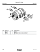

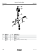
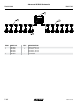

Base Machine Electrical Schematic
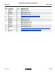
ITEM PART NO. QTY. DESCRIPTION
1 GA19392 1 ISO Extension Cable
2 GA18712 1 Draw Bar Hitch Cable
3 GA19391
GA19390
GA19389
1
-
-
ISO DL 30 Cable, 12 Row
ISO DL 40 Cable, 16 Row
ISO DL 60 Cable, 24 Row
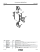
4 --- -
See “Light/Reflective Decal Brackets” on page P195
5 --- -
See “Light/Reflective Decal Brackets” on page P195
6 GA19397 1 Lights Cable
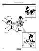
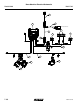
7 GA19412
GA19424
GA19417
1
-
-
ISO PLT Cable, 12 Row
ISO PLT Cable, 16 Row
ISO PLT Cable, 24 Row
8 GA19414
GA19416
GA19420
1
-
-
R.H. Auxiliary Cable, 12 Row
R.H. Auxiliary Cable, 16 Row
R.H. Auxiliary Cable, 24 Row
9 GA19413
GA19415
GA19418
1
-
-
L.H. Auxiliary Cable, 12 Row
L.H. Auxiliary Cable, 16 Row
L.H. Auxiliary Cable, 24 Row
10 --- -
See “Lift Valve Block (Located on Bottom of Valve Block on Wing)” on page P156
11 --- - See “Hydraulic Valve Block on R.H. Wing” on page P157
See “Hydraulic Valve Block on L.H. Wing” on page P158
12 GA19425 Master Module Tech
Model 4900M0247-02
Rev. 11/13 P186
TM