
User Manual
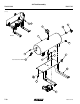
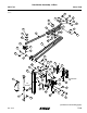

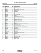

Row Marker Assembly, 16 Row
(A17723a)
Detail A
39
36
19
37
15
38
31
48
1
33 35
52 54
33 35
46
53
46
30
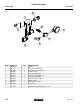
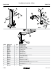
ITEM PART NO. QTY. DESCRIPTION
1 GA18529
GA18530
1 L.H. Outer Breakaway
R.H. Outer Breakaway
2 GA17715 1 First Stage
3 GA18866 1 Second Stage
4 GA18861 1
See “Row Marker Cylinder, 16 Row and 24 Row” on page P130
5 GA17721 1 Third Stage
6 G10108 2 Lock Nut, "-16
7 G10003 2 Hex Head Cap Screw, "-16 x 1½"
8 GA9145 1 Molded Stop, 6¼" Long
9 G10210 2 Washer, " USS
10 GD0453-03 1 Extension Tube, 50"
11 GA13719 1
See "Row Marker Spindle/Hub/Blade" on page P111
12 G10045 1 Hex Head Cap Screw, ½"-13 x 4½"
13 G10844 1 Carriage Bolt, ½"-13 x 3½"
14 G10102 6 Hex Nut, ½"-13
15 G10228 7 Lock Washer, ½"
16 G10168 2 Machine Bushing, ½", 7 Gauge (.1793")
17 GD2721 2 U-Bolt, 2" x 2" x ½"-13
18 GD0704 1 Pin, 1¼" x 14"
19 G10460 5 Cotter Pin, ¼" x 2"
20 GA13485 1 Control Arm
21 G10033 1 Hex Head Cap Screw, ½"-13 x 3½"
22 G10111 3 Lock Nut, ½"-13
23 GD0677 1 Pin, 2" x 15¾"
24 G10461 4 Cotter Pin, " x 3"
25 GD0652 1 Pin, 1¼" x 9½"
26 GD26775 1 Pivot Shaft, 2" x 10½"
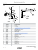
(Continued on the following page.)
Model 4900M0247-02
Rev. 11/13 P106
TM