
User's Manual

Long Range LoRa™ TechnologyTransceiver Module
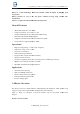
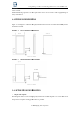
TABLE 2-4:MODULE DIMENSIONS
Parameter
Value
Dimensions 20.3 x 38.8 x
Weight
4.8g
3.0 Typical Hardware
Connections
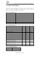
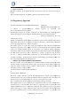
Figure below shows the typical hardware connections.
FIGURE 3-1:
HARDWARE CONNECTIONS
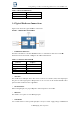
• INTERFACE TO HOST MCU
The KT1276 module has a dedicated UART interface to communicate with a host controller.
Table below shows the default settings for the UART communication.
TABLE 3-
1: DEFAULT UART SETTINGS
Specification
Description
Baud Rate 57600 bps
Packet Length
8 bit
Parity Bit
No
Stop Bits
1 bit
Hardware Flow Control
No
• GPIO PINS
The module has 3 GPIO pins. These lines can be connected to switches, LEDs, and relay outputs.
The pins are either logic inputs or outputs that can be accessed via the module
pins have limited sink and source capabilities.
• RF CONNECTION
When routing RF path, use proper strip lines with an impedance of 50 Ohm.
• RESET PIN
The module’s reset pin is an active-
low logic input.
• POWER PINS
It is recommended to connec
t power pins (Pin 1 and 9) to a stable supply voltage with sufficient
Long Range LoRa™ TechnologyTransceiver Module
KT1276
2017 KingTing Tech. Corporation
Value
3.2 mm
Connections
Figure below shows the typical hardware connections.
HARDWARE CONNECTIONS
The KT1276 module has a dedicated UART interface to communicate with a host controller.
Table below shows the default settings for the UART communication.
1: DEFAULT UART SETTINGS
Description
The module has 3 GPIO pins. These lines can be connected to switches, LEDs, and relay outputs.
The pins are either logic inputs or outputs that can be accessed via the module
firmware. These
pins have limited sink and source capabilities.
When routing RF path, use proper strip lines with an impedance of 50 Ohm.
low logic input.
t power pins (Pin 1 and 9) to a stable supply voltage with sufficient
KT1276
The KT1276 module has a dedicated UART interface to communicate with a host controller.
The module has 3 GPIO pins. These lines can be connected to switches, LEDs, and relay outputs.
firmware. These
t power pins (Pin 1 and 9) to a stable supply voltage with sufficient