
User's Manual

Long Range LoRa™ TechnologyTransceiver Module
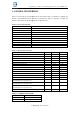
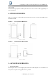
FIGURE
1-
2: KT1276
PIN
DIAGRAM
GND
PA2
PA4
PA1
VCC
RX
TX
NRST
RF
1
2
3
4
5
6
7
8
9
Table 1-1:
describes the module’s pins.
Pin
Name
1
GND
Power
2
PA2
Input/Output
3
PA4
Input/Output
4
PA1
Input/Output
5
RF
RF
analog
6
NRST
Input
7
UART_TX
Output
8
UART_RX
Input
9
VCC
Power
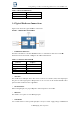
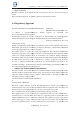
FIGURE
1-
3: KT1276
BLOCK
DIAGRAM
Long Range LoRa™ TechnologyTransceiver Module
KT1276
2017 KingTing Tech. Corporation
describes the module’s pins.
Type
Description
Power
Ground supply terminal
Input/Output
General purpose I/O pin
Input/Output
General purpose I/O pin
Input/Output
General purpose I/O pin
analog
RF signal pin
Active-low device Reset input
Output
Communication UART Transmit (TX)
Communication UART Receive (RX)
Power
Positive supply terminal
KT1276