KINGSTON TECHNOLOGY EtheRx 4-PORT AND 8-PORT WORKGROUP 100BASE-TX FAST ETHERNET HUBS USER’S GUIDE MODELS: KNE4TX/WG KNE8TX/WG
i Kingston Technology’s EtheRx Workgroup 4-Port and 8-Port 100BASE-TX Fast Ethernet Hubs User’s Guide Part No. 4460057-001.A00 Kingston Technology Company 17600 Newhope Fountain Valley, CA 92708 (714) 435-2600 KNExTX/WG User’s Guide - Rev.
ii TABLE OF CONTENTS Introduction...................................................................................... 1 Model Types...................................................................... 1 Special Features ............................................................... 2 Package Contents............................................................. 2 Design Features .............................................................................. 3 Repeater Functions...........................
iii Appendix B Cabling Guidelines ....................................11 UTP Cable Wiring .............................................11 Cable Wiring Standards ....................................11 Rating Codes ....................................................13 Appendix C Specifications............................................14 Appendix D Commonly Asked Questions.....................16 Appendix E Mounting Templates..................................17 Appendix F Warranties and Notices ...
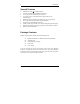
Introduction 1 Introduction Intended Audience: This manual assumes that the user has a general working knowledge of networking principles and architecture and is familiar with network systems in general. Congratulations on the purchase of your Kingston EtheRx WorkGroup (WG) series 100BASE-TX Fast Ethernet hubs. There are two models available in this series: KNE4TX/WG, which is the 4-Port model, and KNE8TX/WG, which is the 8-Port model.
2 Introduction Special Features • • • • • • • • • • 100BASE-TX Class II compliant repeater Conforms to IEEE802.
Design Features 3 Design Features The EtheRx hub complies with the full set of repeater basic functions as defined by IEEE 802.3u. These functions include all Repeater Functions, Signal Regeneration, Receive Jabber Protection, Collision-Handling, ErrorHandling, and Auto Partitioning/Reconnection. Repeater Functions If any single port senses the start of a valid packet on its receiving line, the EtheRx hub will re-transmit the received data to all other ports on the network.
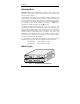
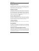
4 Front Panel Hardware Installation Before you begin installing network cables, please take a few moments to familiarize yourself with the EtheRx hubs. The front and rear panels of the Fast Ethernet Workgroup hubs are illustrated below. Front Panel Utilization LEDs I00BASE-TX Class UTP Port LEDs EtheRx Workgroup Repeater UTIL % PWR KNE4TX/WG 1 12 25 LINK / ACTIVITY / PARTITION 50 Power LED 1 COLL 60 2 3 4 CASCADE Collision LED Cascade Switch Fig.
Front Panel 5 Utilization LEDs The five Utilization LEDs display the rate of network traffic in percentages of the total available bandwidth. The amount of data traffic is measured in frames per second (FPS), then calculated into percentage values: 1%, 12%, 25%, 50%, and > 60%. The appropriate LED will light up based on network activity. Collision LED If a collision is detected on the network, the Collision LED will flash amber.
6 Front Panel Cascade Switch The Cascade Switch provides cable wiring flexibility on the last UTP Port (i.e., Port 4 or Port 8) for connecting to a workstation or cascading to another hub. By default, the last UTP port is set to “Crossover” (left side) as a standard, internally-crossed port, or MDI-X port. Depending on the wiring of your UTP cable (normally “Straight-Through”), the port is used to connect a workstation.
Front Panel 7 Port 1 through Port 3 (or 7) respectively, like all normal hub ports, are configured MDI-X, whereas the last UTP ports, Port 4 or Port 8, support both port configurations, MDI and MDI-X. All NICs (Network Interface Cards) and Router ports are usually by default configured MDI.
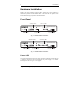
8 Rear Panel Rear Panel 5V 4 3 2 2A 1 Fig. 1-6 KNE4TX/WG Rear Panel 5V 8 7 6 5 3 4 2 2A 1 Fig. 1-7 KNE8TX/WG Rear Panel 4 or 8 UTP Ports The UTP ports are numbered 1 through 4 or 1 through 8 for 100BASE-TX connections. Since crossover function is implemented on all UTP MDI-X ports, a straight-through UTP cable should be used. (Note: Port 4 and Port 8 support both cable types using the cascade switch. Refer to Appendix A & B for details on RJ-45 pin assignments and cable guidelines.
Appendices 9 Appendices KNExTX/WG User’s Guide - Rev.
10 Appendix A Appendix A Pin Assignments Pin Assignments UTP Pin Assignments UTP Ports use RJ-45 Unshielded Twisted Pair (UTP) cabling. Cable Pin Numbers and Pin Wiring Assignments are listed below in Figure A-1 and Table A-2, respectively. Twisted-Pair cables can be wired with either StraightThrough or Crossover pin assignments. Both wiring schemes are mentioned in "Appendix B Cabling Guidelines" for reference in creating a twisted-pair cable. 5V 3 2 2A 1 1 2 3 4 5 6 7 8 Fig.
Appendix B Cabling Guidelines Appendix B 11 Cabling Guidelines UTP Cable Wiring 100BASE-TX unshielded twisted-pair cables can be wired as "StraightThrough" or, in some cases, "Crossover" depending on the application. For workstations connected to a hub, use "Straight-Through' wiring illustrated in Table B-1. In some instances, you may want to use "Crossover" wiring illustrated below in Table B-2.
12 Appendix B Cabling Guidelines Pair 2 Pair 3 Pair 3 Pair 1 Pair 4 Pair 2 Pair 1 Pair 4 12345678 12345678 T568A T568B Fig. B-1 4-Pair T568A Wiring Fig.
Appendix B Cabling Guidelines 13 Rating Codes UTP cables meet different UL-NEC requirements based on cable-jacket quality. Below is an explanation of the rating codes for each cable type. UL – The National Electrical Code (NEC), published by the National Fire Protection Association (NFPA), details advisory safety considerations for electrical wiring. NEC Article 800 Communications Cables are manufactured to meet these different cable types. 1.
14 4. Appendix B Cabling Guidelines NEAR-END CROSSTALK (NEXT) – In wires packed together within a cable, the signals generated at one end of the link can flush out the weaker signals coming back from the recipient. Appendix C Specifications EtheRx 4- and 8-Port Fast Ethernet Workgroup Hubs Compliance: Media Interface: KNE4TX/WG KNE8TX/WG Diagnostic LEDs: 1 LED for each port Connection Type: Cable Type: Maximum Cable Length: Cascading 2 Class II repeaters (2 max.
Appendix D Commonly Asked Questions EMI Standards: EMC Standards: Low Voltage Directive: 15 FCC Class A, CE CISPR A EN55022, IEC801-2, IEC801-3, IEC801-4 EN60950 KNExTX/WG User’s Guide - Rev.
16 Appendix D Appendix D Commonly Asked Questions Commonly Asked Questions Class I vs. Class II 100BASE-TX Fast Ethernet Repeaters There are currently two classes of Fast Ethernet repeaters, defined as Class I and Class II . Class I : in a maximum length segment topology, only one Class I repeater may exist between any two nodes within a single collision domain. Class II : in a maximum length segment topology, two Class II repeaters may exist between any two nodes within a single collision domain.
Appendix D Commonly Asked Questions 17 Category 5 Compliance vs. Category 5 Performance? Having CAT 5 components in your network installation does not necessarily achieve full Category 5 performance. To achieve any category-rated performance, make sure all cabling components are at least of the minimum category required. To achieve full CAT 5 performance, all components must be CAT 5 compliant and terminated properly according to EIA/TIA-568 TSB-36 and TSB-40 guidelines.
18 Appendix D Mounting Templates The EtheRx WorkGroup hubs can be stationed on a flat surface using the four rubber feet provided, or mounted vertically by using the mounting holes on the bottom side of the unit. The illustrations below detail the measurements and mounting holes and rubber feet locations. They are drawn to scale, although not actual size. Front Panel 1.08" Wall Mount Holes 4.28" 2.95" 5.95" Rubber Feet Rubber Feet Rear Panel 6.
Appendix F Warranties and Notices Appendix F 19 Warranties and Notices Limited Warranty Statement KINGSTON TECHNOLOGY COMPANY ("Kingston") warrants that this product is free from defects in material and workmanship. Subject to the conditions and limitations set forth below, Kingston will, at its option, either repair or replace any part of this product which proves defective by reason of improper workmanship or materials.
20 Appendix F Warranties and Notices Warranty Claim Requirements To obtain warranty service, return the defective product, freight prepaid and insured, to your local authorized Kingston dealer or distributor, or to the Kingston factory service center located at 17600 Newhope Street, Fountain Valley, California 92708, U.S.A. You must include the product serial number (if applicable) and a detailed description of the problem you are experiencing.
Appendix F Warranties and Notices 19 F.C.C. Certification This device has been tested and found to comply with limits for Class A digital device, pursuant to Part 15 of the FCC Rules. Operation is subject to the following two conditions: (1) This device may not cause harmful interference, and (2) This device must accept any interference received; including interference that may cause undesired operation.