
User Manual


DS3234
Extremely Accurate SPI Bus RTC with
Integrated Crystal and SRAM
_____________________________________________________________________ 5
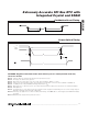
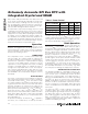
Pushbutton Reset Timing
t
RST
PB
DB
RST
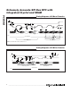
Power-Switch Timing
V
CC
V
PF(MAX)
RST
V
PF(MIN)
t
VCCF
t
VCCR
t
REC
V
PF
V
PF
Note 2: Limits at -40°C are guaranteed by design and not production tested.
Note 3: All voltages are referenced to ground.
Note 4: Measured at V
IH
= 0.8 x V
CC
or V
IL
= 0.2 x V
CC
, 10ns rise/fall time, DOUT = no load.
Note 5: Current is the averaged input current, which includes the temperature conversion current. CRATE1 = CRATE0 = 0.
Note 6: The RST pin has an internal 50kΩ (nominal) pullup resistor to V
CC
.
Note 7: Measured at V
OH
= 0.8 x V
CC
or V
OL
= 0.2 x V
CC
. Measured from the 50% point of SCLK to the V
OH
minimum of DOUT.
Note 8: With 50pF load.
Note 9: The parameter t
OSF
is the period of time the oscillator must be stopped for the OSF flag to be set over the voltage range of
0V ≤ V
CC
≤ V
CC(MAX)
and 2.3V ≤ V
BAT
≤ V
BAT(MAX)
.
Note 10: This delay only applies if the oscillator is enabled and running. If the EOSC bit is 1, t
REC
is bypassed and RST immediately
goes high.
Note 11: Guaranteed by design and not production tested.
WARNING: Negative undershoots below -0.3V while the part is in battery-backed mode may
cause loss of data.