
User Manual
D03Rev2.3
9
DMT proprietary & confidential: product information is subject to change without notice.
Domintech Co., Ltd. Tel: +886-2-2290-1288 Fax: +886-2-2290-1266 http://www.domintech.com.tw
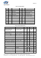
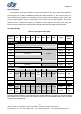
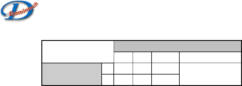
Table 8: Bandwidth Table
N[1:0] (08h:bit1, 0)
Hz
00 01 10 11
0
19 38 76
Tms
(08h: bit2)
1
38 76 153
No Filter
High-G Detection
HGXEn, HGYEn, HGZEn (09h:bit6, 5, 4) are the X-, Y-, and Z-axis high-G interrupt enable control
bits respectively. If the respective high-G interrupt enable bit is set to 1, high-G monitoring is enabled
for the respective axis. Upon enabled, DMARD03 will check closely if the acceleration magnitude of
the respective axis exceeds some high-G threshold value. Furthermore the HGAO (09h:bit7) serves as
the logical combination control bit for multiple axial detections. Logic-1 HGAO will do “logic-AND” of
enabled multiple axial detections before output to the configured interrupt pin INT×. On the contrary,
logic-0 HGAO will do “logic-OR” of enabled multiple axial detections before output to the configured
interrupt pin INT×. Logic-1 INT× stands for high-G event detection and logic-0 otherwise. The INTx pin
will directly reflect the detection result, in other words the result is not latched. The high-G interrupt flag
(HGInt, 0Ch:bit6) serves the same purpose and manner as the INTx pin. This flag can be read via the
SPI/I2C digital interface, and therefore is an alternative to the INTx pin if end users have GPIO
constraint.
In the case when the enabled multiple axial detections are logic-OR’ed (HGAO is logic-0), we may
want to further identify which axis and direction cause the high-G detection. This can be achieved by
first latching the result and then checking direction flags. Logic-1 HGL(08h:bit3) will cause the high-G
detection results latched. Then high-G direction flags (XHGP, XHGN, YHGP, YHGN, ZHGP, ZHGN,
0Ch:bit5~0) can be checked to detail the high-G axis and direction upon high-G detection. The latch
will be automatically cleared after the high-G flag register (0Ch) is read. Following summarizes the
meaning when respective flag is set.
1. XHGP: high-G detected in the X-axis positive direction
2. XHGN: high-G detected in the X-axis negative direction
3. YHGP: high-G detected in the Y-axis positive direction
4. YHGN: high-G detected in the Y-axis negative direction
5. ZHGP: high-G detected in the Z-axis positive direction
6. ZHGN: high-G detected in the Z-axis negative direction
Please note that when the enabled multiple axial detections are logic-AND’ed (HGAO is logic-1)
the high-G latch (HGL is logic-1) is not supported. The outcome may not be repeatable when HGAO
and HGL are both set.
For INT× configuration, see “INT1 and INT2 Source Configure”. User can set respective high-G
threshold, see "High-G Threshold" for details. For high-G interrupt and direction flags, see "Interrupt
Status Registers" for details. For high-G latch, see “High-G Latch Control” for details.