
User Manual

D03Rev2.3
7
DMT proprietary & confidential: product information is subject to change without notice.
Domintech Co., Ltd. Tel: +886-2-2290-1288 Fax: +886-2-2290-1266 http://www.domintech.com.tw
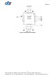
Data Registers
Temperature and acceleration output values can be read from the data registers. The sensor
output is converted to an 11-bit value and stored across two register bytes. Data representation is 2's
complement, i.e. MSB 1 means negative values. Data is periodically updated with sampling period
which is user-settable, and data registers will keep their values intact when digital interface (SPI or
I2C) is accessed. In addition the data can be pre-processed by digital moving average filter for
bandwidth control. Please refer to "Control Registers" for more details on the sampling period and
bandwidth control.
A thermometer is embedded in DMARD03. Its temperature sensitivity is 16 LSB/°C and the
central value (0h) stands for 25°C. For example a Tout[10:0] reading of 80h means 25+80h/16=33°C.
The acceleration sensitivity is 256 LSB/g and the central value (0h) stands for 0g. For example a
Xout[10:0] reading of 100h means 100h/256=1g.
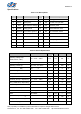
Following lists the summary of sensor output and data registers:
1. Tout[10:0]: 11-bit temperature output, register 00h:bit7~0 + 01h:bit2~0
2. Xout[10:0]: 11-bit X-axis output, register 02h:bit7~0 + 03h:bit2~0
3. Yout[10:0]: 11-bit Y-axis output, register 04h:bit7~0 + 05h:bit2~0
4. Zout[10:0]: 11-bit Z-axis output, register 06h:bit7~0 + 07h:bit2~0
Control Registers
INT1 and INT2 Source Configure
I1CFG[1:0] (08h:bit5, 4) and I2CFG[1:0] (08h:bit7, 6) are interrupt pins (INT×, ×=1, 2) source
configuration bits respectively. DMARD03 has two interrupt pins configurable from three interrupt
sources of freefall, click and high-G. Each interrupt INT× has two bits to configure its output from any of
the three interrupt sources, or alternatively turn it off by grounding. The INTx source configuration table
can be found in Table 5.
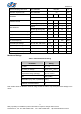
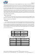
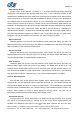
Table 5: INTx Pin Source Configuration Table
IxCFG[1]
x=1, 08h:bit5
x=2, 08h:bit7
IxCFG[0]
x=1, 08h:bit4
x=2, 08h:bit6
INTx Source
0 0 GND
0 1 Freefall
1 0 Click
1 1 High-G
Note: x=1, 2
Freefall Interrupt Enable
IxCFG[1:0] has a side effect on the freefall interrupt enable control. If either pin of INTx is
configured to source its output from freefall, i.e. IxCFG[1:0] = 01b, the freefall interrupt is automatically