
User Manual

D03Rev2.3
18
DMT proprietary & confidential: product information is subject to change without notice.
Domintech Co., Ltd. Tel: +886-2-2290-1288 Fax: +886-2-2290-1266 http://www.domintech.com.tw
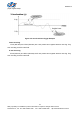
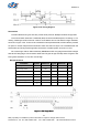
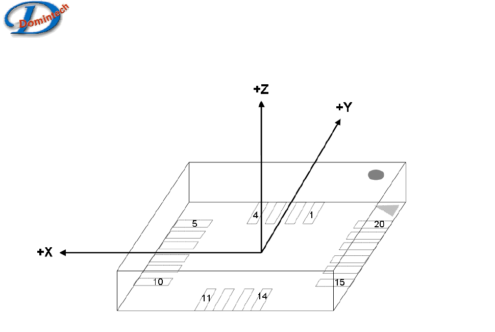
Axes Orientation
Figure 12: Axes Orientation of DMARD03
RoHS Compliance
The 20-pin LGA package conforms to the EU directive on the restriction of the use of certain
hazardous substances in electrical and electronic equipment 2002/95/EC.
Surface Mounting Information
The accelerometer is sensitive to the mechanical and thermal stress, so proper PCB board design and
well-executed soldering processes are crucial to ensure consistent performance. Below summarized
the guidelines for the surface mounting technology:
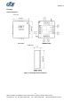
1. The layout dimension of the PCB land pad and SR open should follow the recommendation in
Figure 13.
2. The placement of accelerometer should not be within the vicinity of mechanical screws, fasteners,
fixtures, and etc. The kept distance is to diminish the mechanical stress influence.
3. The area underneath the accelerometer package should be clear of any top copper traces and
any structure like via. It is to ensure the planarity and reduce the potential board stress.
4. The trace connected to the land pad should be as symmetric as possible.
5. Do not place any components, buttons, shielding case or via at a distance less than 2mm from
the accelerometer package land area. This is to prevent mechanical stress or large thermal
sink/source to the adverse of sensor performance.
6. Use a typical pick-and-place machine with reflow equipment like oven. Avoid any manual
soldering process.
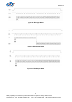
7. We recommend using a no-clean solder paste for the surface mounting process. Figure 14
should be referred for proper soldering temperature profile control.
8. Offset shift may exist after the accelerometer being mounted onto the PCB board. It depends on