
User Manual

D03Rev2.3
13
DMT proprietary & confidential: product information is subject to change without notice.
Domintech Co., Ltd. Tel: +886-2-2290-1288 Fax: +886-2-2290-1266 http://www.domintech.com.tw
Digital Interface
DMARD03 provides two digital interfaces (SPI 4-wire and I2C) and an interrupt output signal for
easy configuration and data/status query. The digital interface can be used to regularly read the data
registers of acceleration and temperature output. The DMARD03 can also be configured by setting up
proper control registers via the digital interface. For example, the interrupt pin can be configured to
response to freefall or click event. Upon triggered interrupt, user can use the digital interface to check
the interrupt status register for proper interrupt source verification.
I2C Interface
DMARD03 includes a slave I2C interface. CS must be connected to ground when choosing I2C as
digital interface. The I2C bus takes master clock through SCL pin and exchanges serial data via SDI.
SDI is bidirectional (input/output) with open drain. It must be connected externally to VIF via a pull-up
resistor. SDO is used to set I2C slave address SDO-bit. The SDO-bit can be set to 1 by connecting
SDO to VIF, or to 0 by grounding.
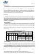
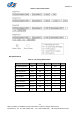
I2C Slave Address
DMARD03 has a 7-bit slave address. The six high bits is fixed at value 001110b. The LSB of slave
address (bit1 or SDO-bit) can be set to either 1 or 0 by physical SDO connection. For example if SDO
is connected to high (VIF), the 7-bit slave address is 0011101b, and vice versa. Additional RW bit sets
the chip in read or write mode, RW = 0 for write and 1 for read. Table 8 summaries the I2C slave
address and RW.
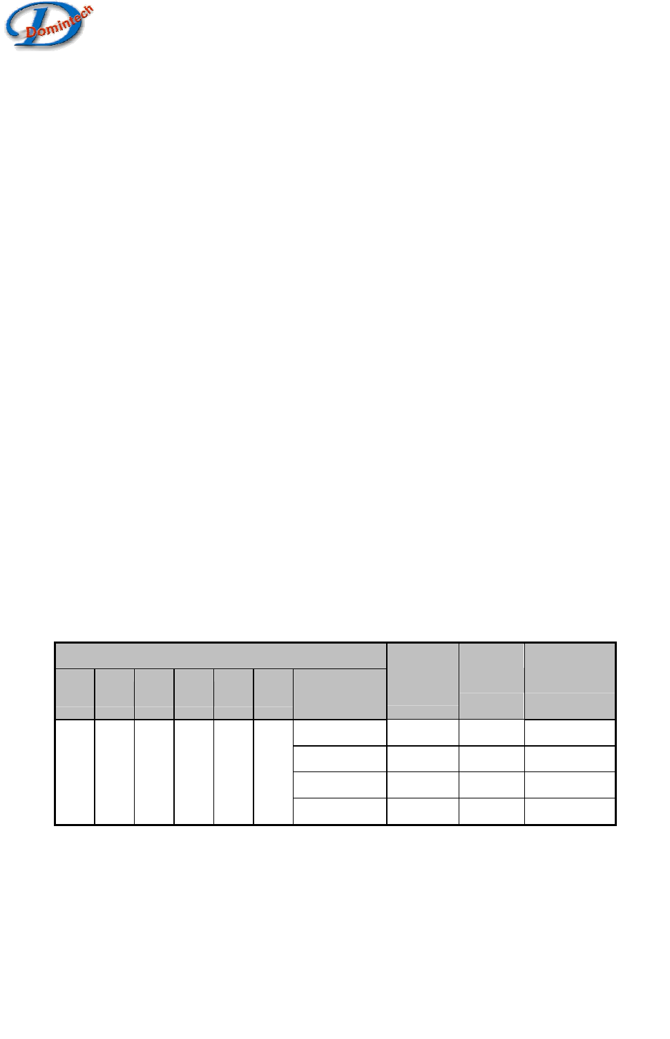
Table 9: I2C slave address & RW
Slave Address
bit7
bit6
bit5
bit4
bit3
bit2
bit1
(SDO-bit)
bit0
(RW)
Hex Read/Write
0 0 38h Write
0 1 39h Read
1 0 3Ah Write
0 0 1 1 1 0
1 1 3Bh Read
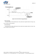
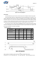
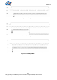
I2C Access Format
Data transfer begins by bus master indicating a start condition (ST) of a falling edge on SDI when
SCL is high. Stop condition (SP) also indicated by bus master is a rising edge on SDI when SCK is high.
After a start condition, the slave address + RW bit must be sent by master. If the slave address does
not match with DMARD03, there is no acknowledge and the following data transfer will not affect
DMARD03. If the slave address corresponds to DMARD03, it will acknowledge by pulling SDI to low and
the SDI line is let free enabling the data transfer. The master should let the SDI high (no pull down) and
generate a high SCL pulse for DMARD03 acknowledge.